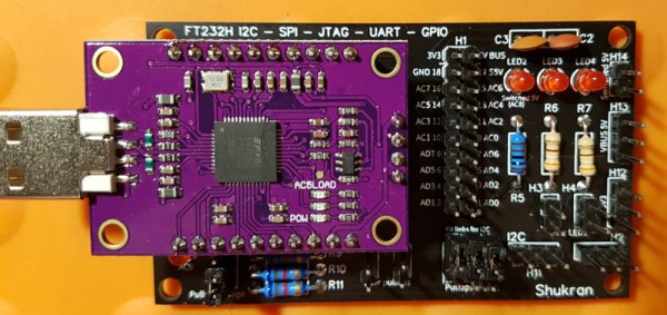
We’d wager most hackers are familiar with FTDI as the manufacturer of the gold standard USB-UART interfaces. Before parts like the ultra cheap CH340 and CP2102 became common, if you needed to turn a USB cable into a TTL UART device, “an FTDI” (probably an FT232RL) was the way to make that happen. But some of the parts in the FT232* family are capable of much more. Wanting to get at more than a UART, [linker3000] designed the Shukran to unlock the full potential of the FT232H.
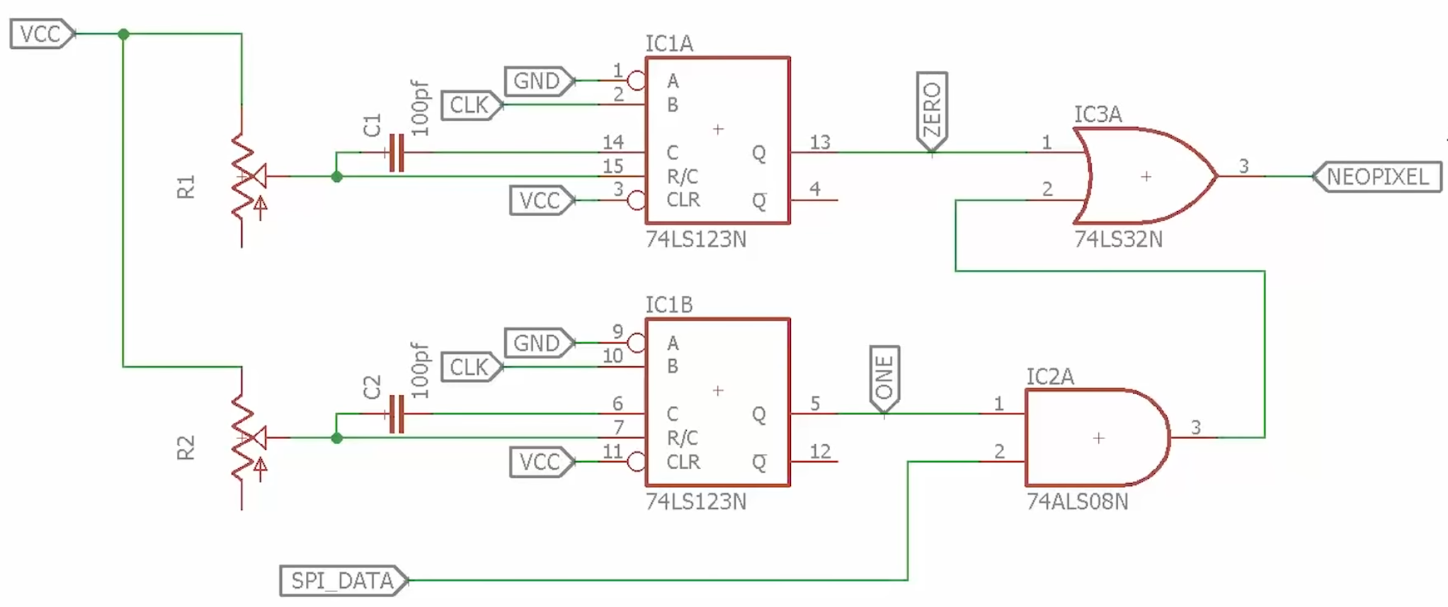
 The FT232H is interesting because it’s an exceptionally general purpose interface device. Depending on configuration it can turn USB into UART, JTAG, SPI, I2C, and GPIO. Want to prototype the driver for a new sensor? Why bother flashing your Teensy when you can drive it directly from the development machine with an FT232H and the appropriate libraries?
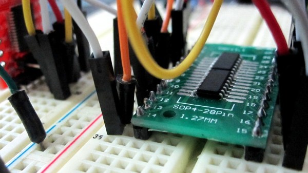
The Shukran is actually a breakout for the “CJMCU FT232H” module available from many fine internet retailers. This board is a breakout that exposes a USB-A connecter on one side and standard 0.1″ headers on the other, with a QFN FT232H and all the passives in the middle. But bare 0.1″ headers (in a square!) require either further breadboarding or a nest of jumper wires to be useful. Enter the Shukran. In this arrangement, the CJMCU board is cheap and handles the SMT components, and the Shukran is easy to assemble and makes it simple to use.
The Shukran gives you LEDs, buttons and switches, and a bunch of pull up resistors (for instance, for I2C) on nicely grouped and labeled headers. But most importantly it provides a fused power supply. Ever killed the USB controller in your computer because you forgot to inline a sacrificial USB hub? This fuse should take care of that risk. If you’re interested in building one of these handy tools, sources and detailed BOM as well as usage instructions are available in the GitHub repo linked at the top.