This Vintage Alphanumeric Display Was Huge, Hot, Heavy, And Expensive

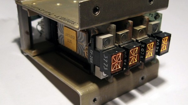
It’s easy to take display technology for granted nowadays, but the ability to display data in a human-readable way was not always easy. This is demonstrated well by the Pinlite 30003 Alphanumeric Display Module, a four-character display that was pure luxury for its time.

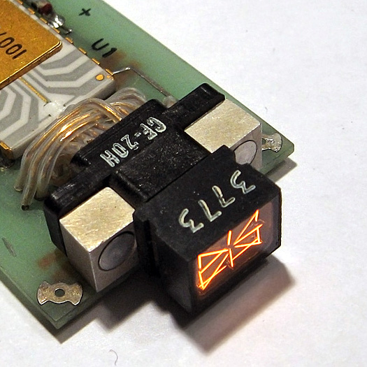
Each display is a rectangular vacuum tube containing 17 incandescent light filaments.

Not only were the 17 segments that make up each display capable of showing any letter or number, but they were even daylight-readable! Each of those 17 segments is an incandescent lamp filament, which is how the required brightness was achieved. The sturdy module shown here holds four such displays, each of which is on its own pluggable board with a dedicated character decoder chip directly behind it.

As [AnubisTTL] points out, the resulting unit is bulky, has terrible character spacing, and was no doubt very costly. By today’s standards, it is almost unimaginably heavy, hot, and impractical. But before high-brightness LEDs were a thing, a daylight-readable alphanumeric character display was really something special. It would absolutely have been worth the money and effort to the right people.

Before small and efficient displays were commonplace, the solution to the problem of how to display data efficiently and in an easy-to-read format took a lot of really unusual (and clever) turns as engineers worked around the limitations of the time. This resulted in oddities like the SD-11 Sphericular Display, which is mostly empty space on the inside. Another great example is the Eidophor, a projector from before projectors were even a thing.

Integrated Circuit Manufacturing At Bell Labs In 1983

With the never ending march of technological progress, arguably the most complex technologies become so close to magic as to be impenetrable to those outside the industry in which they operate. We’ve seen walkthrough video snapshots of just a small part of the operation of modern semiconductor fabs, but let’s face it, everything you see is pretty guarded, hidden away inside large sealed boxes for environmental control reasons, among others, and it’s hard to really see what’s going on inside.

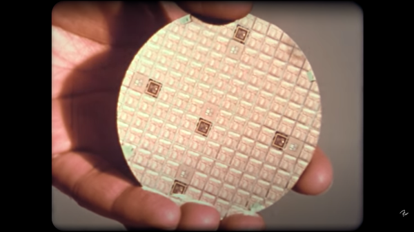
Let’s step back in time a few decades to 1983, with an interesting tour of the IC manufacturing facility at Bell Labs at Murray Hill (video, embedded below) and you can get a bit more of an idea of how the process works, albeit at a time when chips hosted mere tens of thousands of active devices, compared with the countless billions of today. This fab operates on three inch wafers, producing about 100 die each, with every one handled and processed by hand whereas modern wafers are much bigger, die often much smaller with the total die per wafer in the thousands and are never handled by a filthy human.

Particle counts of 100 per cubic foot might seem laughable by modern standards, but device geometries back then were comparatively large and the defect rate due to it was not so serious. We did chuckle somewhat seeing the operator staff all climb into their protective over suits, but open-faced with beards-a-plenty poking out into the breeze. Quite simply, full-on bunny suits were simply not necessary. Anyway, whilst the over suits were mostly for the environment, we did spot the occasional shot of an operator wearing some proper protective face shielding when performing some of the higher risk tasks, such as wafer cleaning, after all as the narrator says “these acids are strong enough to eat through the skin” and that would certainly ruin your afternoon.

No story about integrated circuit processing would be complete without mentioning the progress of [Sam Zeloof] and his DIY approach to making chips, and whilst he’s only managing device counts in the hundreds, this can only improve given time.

Continue reading “Integrated Circuit Manufacturing At Bell Labs In 1983”

Want To Use A Classic Mac Mouse On A Modern Computer? No? Here’s How To Do It Anyway

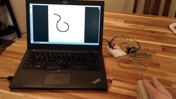
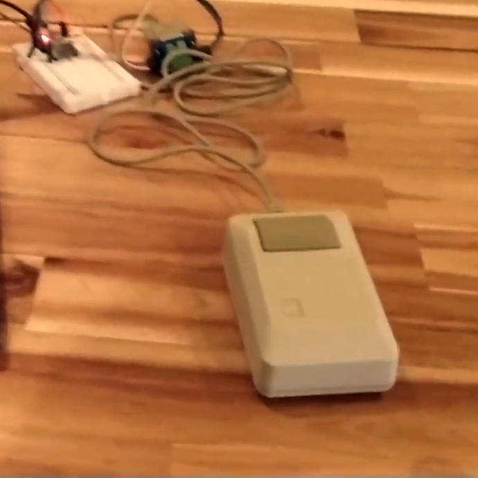
Need to hook a classic Mac mouse up to your modern machine with the help of a DIY USB adapter? [John Floren] has you covered. [John]’s solution uses a board with an ATmega32U4 microcontroller on it to connect to the Mac mouse on one end, and emulate a USB HID (Human Interface Device) on the other. A modern machine therefore recognizes it like it would any other USB input device.

Why is this necessary? The connector on the classic Mac mouse may look like a familiar DE-9 connector, but it is not an RS-232 device and wouldn’t work if it were plugged into a 9-pin serial port. The classic Mac mouse uses a different pinout, and doesn’t have much for brains on the inside. It relies on the host computer to read its encoders and button states directly.

This project is actually a bit of an update to a piece of earlier work [John] did in making a vintage Depraz mouse work with modern systems. He suspected that it wouldn’t take much to have it also work with a classic Mac mouse, and he was right — all it took was updating the pin connections and adding some pull-up resistors. The source code and design files are on GitHub.

Even if one does not particularly want to use a classic Mac mouse for daily work, there’s definitely value in this kind of thing for those who deal in vintage hardware: it allows one to function-check old peripherals without having to fire up a vintage machine.

Continue reading “Want To Use A Classic Mac Mouse On A Modern Computer? No? Here’s How To Do It Anyway”

Building A Tube-Based Stereo Amp, In Classic Style

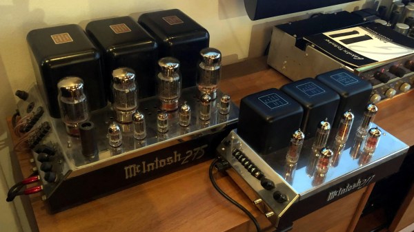
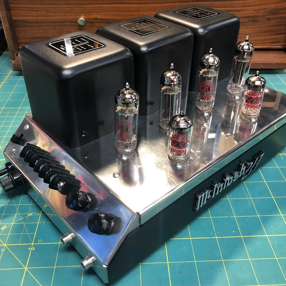
It’s not every day we see the results of someone putting their own spin on a vintage tube amp, but that’s exactly what [lens42] did in creating the McIntosh 217, created as a “mini” version of the McIntosh MC275, a classic piece of audio equipment. Both are pictured next to each other, above.

When it comes to vintage hi-fi stereo amplifiers, two units had particular meaning for [lens42]: the McIntosh MC275 Power Amp, and the Dynaco ST35. The Dynaco was a more budget-friendly amplifier, but looked like a plain box. The McIntosh, however, proudly showed off its tubes and transformers in all their glory. The “McIntosh 217” is design-wise basically a smaller McIntosh MC275, with the innards of a Dynaco ST35.

With so much needing to be designed from the ground up, CAD was invaluable. Component layout, enclosure design, and even wiring and labeling all had to be nailed down as much as possible before so much as heating up the soldering iron. Even so, there were a few hiccups; a vendor had incorrect measurements for a tube socket which meant that the part would not fit. A workaround involved modifying the holes and as luck would have it, the change wasn’t an eyesore. Still, [lens42] reminds us all that whenever you can, have the required parts in-hand for confirmation of dimensions before sending CAD files off for cutting or fabrication.

Many of us can relate to the fact that the whole project was a labor of love and made no real financial sense, but the end result is fantastic, and creating such a thing is something all of us — not just chasers of that elusive “tube sound” — can appreciate.

Fix Old Caps, But Keep That “Can Capacitor” Look

Vintage electronics and capacitor replacements tend to go hand-in-hand. Why? Because electrolytic capacitors just don’t last, not the way most other components do, anyway.

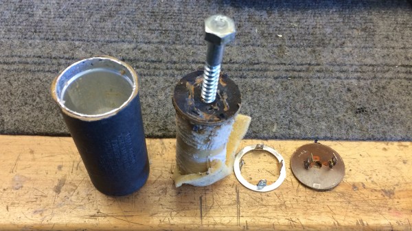
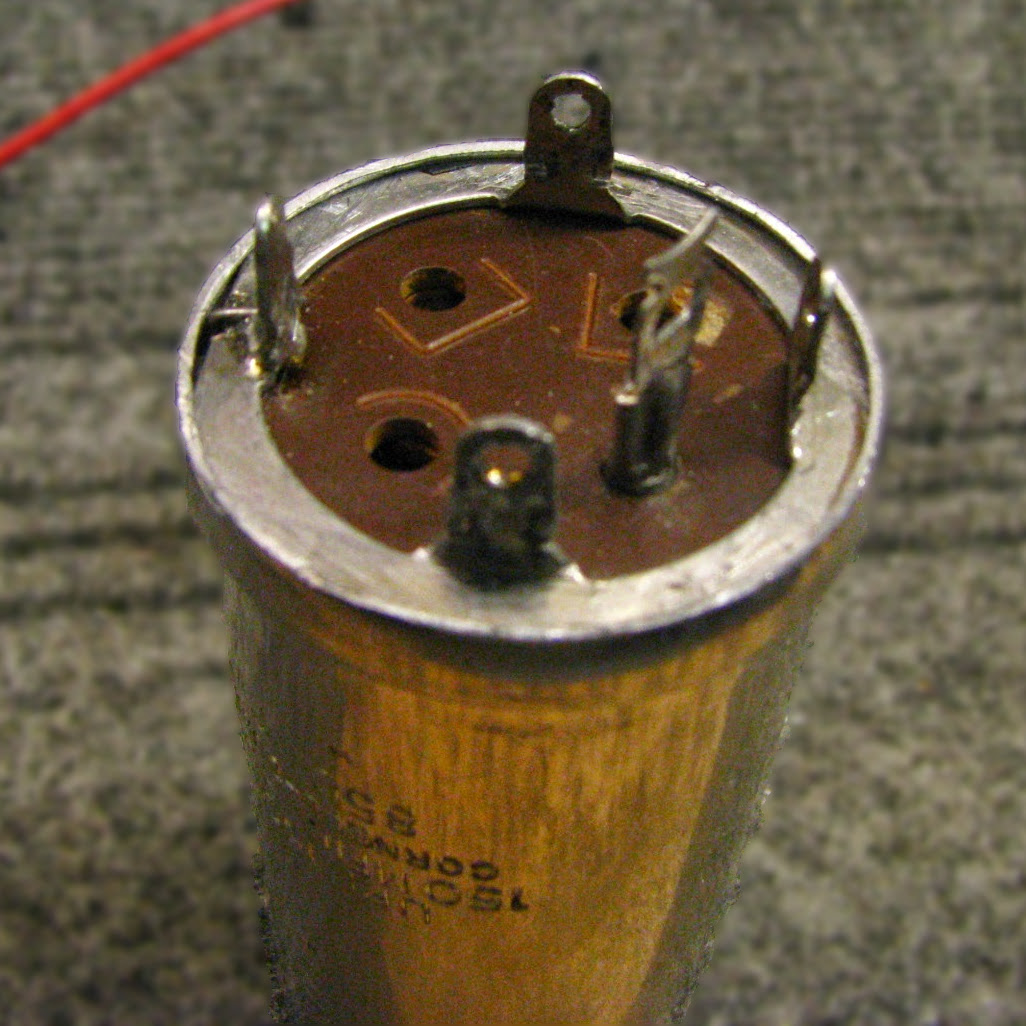
The metal terminal ring and the central plate are kept for re-use, and the metal case re-crimped after the internals of the capacitor are replaced with a modern equivalent.

It’s one thing to swap old caps with modern replacements, but what about electronics where the components are not hidden away, and are an important part of the equipment’s look? [lens42] shares a method for replacing antique can-style capacitors in a way that leaves them looking completely original. All it takes is some careful application of technique.

The first thing to do is carefully file away the crimp of the metal can until one can release the ring and plate that hold the terminals. Once that is off, the internals can be pulled from the metal can for disposal. Since the insides of the old cap won’t be re-used, [lens42] recommends simply drilling a hole, screwing in a lag bolt to use as a handle, and pulling everything out. There’s now plenty of space inside the old can to hold modern replacements for the capacitor, and one can even re-use the original terminals.

That leaves the job of re-crimping the old can around the terminal ring to restore a factory-made appearance. To best do this, [lens42] created a tapered collar. Gently hammering the can forces the bottom into the taper, and the opening gradually crimps around the terminal ring. It’s also possible to carefully hammer the flange directly, but the finish won’t be as nice. This new crimp job may not look exactly the same as before, but once the cap is re-installed into the original equipment, it won’t be possible to tell it has been modified in any way.

If this sounds a bit intimidating, don’t worry. [lens42] provides plenty of pictures. And if this kind of thing is up your alley, you may want to check out the Caps Wiki, an effort to centralize and share details about tech repair, especially for vintage electronics.

A ’70s TV With ’20s Parts

Keeping older technology working becomes exponentially difficult with age. Most of us have experienced capacitor plague, disintegrating wire insulation, planned obsolescence, or even the original company failing and not offering parts or service anymore. To keep an antique running often requires plenty of spare parts, or in the case of [Aaron]’s vintage ’70s Sony television set, plenty of modern technology made to look like it belongs in a machine from half a century ago.

The original flyback transformer on this TV was the original cause for the failure of this machine, and getting a new one would require essentially destroying a working set, so this was a perfect candidate for a resto-mod without upsetting any purists. To start, [Aaron] ordered a LCD with controls (and a remote) that would nearly fit the existing bezel, and then set about integrating the modern controls with the old analog dials on the TV. This meant using plenty of rotary encoders and programming a microcontroller to do the translating.

There are plenty of other fine details in this build, including audio integration, adding modern video and audio inputs like HDMI, and adding LEDs to backlight the original (and now working) UHF and VHF channel indicators. In his ’70s-themed display wall, this TV set looks perfectly natural. If your own display wall spotlights an even older era, take a look at some restorations of old radios instead.

Continue reading “A ’70s TV With ’20s Parts”

The Tools That Lovingly Tore Apart A Vintage Computer Game

The structure of computer game assets can be a bit of a mystery, even more so the older a game is, and some amount of reverse-engineering can be expected when pulling apart a game like 1995’s Night Light.

[voussoir] had fond memories of this game by GTE Entertainment, which had an interesting “flashlight” mechanic to serve the exploration theme. Spooky shapes in dark rooms would be revealed to be quite ordinary (and therefore not scary at all) once illuminated with a flashlight, which was directed by the mouse.

Extracting game assets was partly straightforward, thanks to many of them being laid out in a handy folder structure, with .bmp files for each level in a modest resolution. But there were also some unusual .mov files that were less than a second long, and those took a little more work to figure out.

It turns out that these unusual movie files were 80 frames in length, and each frame was a tile of a larger image. [voussoir] used ffmpeg to extract each frame, then wrote a Python script to stitch the tiles together. Behold! The results are high-resolution versions of each level’s artwork. Stitching the first 16 frames into a 4×4 grid yields a 1024×768 image, and the remaining 64 frames can be put into a 8×8 grid for a fantastic 2048×1376 version. The last piece was extracting audio, but sadly the ISO [voussoir] was using seems to have had errors, and not all the audio survived.

With intact assets in hand, [voussoir] was able to re-create the core of the game, which can be seen about halfway down into the writeup. Audio clues play simply while the flashlight effect is re-created in the browser with the game’s original level artwork, and it’s enough to ring those nostalgia bells. It’s a pretty successful project, even though not all of the assets have been tracked down, and not all of the audio was able to be extracted due to corruption. If you have any insights on that front, don’t keep them to yourself! Send [voussoir] an email, or chime in here in the comments.

Reverse engineering has a strong history when it comes to games, and has manifested itself in sometimes unusual ways, like the time Atari cracked the NES. Had the subsequent legal challenge gone differently, the game landscape might have looked very different today.