DIY Wireless Serial Adapter Speaks (True) RS-232

There is a gotcha lurking in wait for hackers who look at a piece of equipment, see a port labeled “Serial / RS-232”, and start to get ideas. The issue is the fact that the older the equipment, the more likely it is to be a bit old-fashioned about how it expects to speak RS-232. Vintage electronics may expect the serial data to be at bipolar voltage levels that are higher than what the typical microcontroller is used to slinging, and that was the situation [g3gg0] faced with some vintage benchtop equipment. Rather than deal with cables and wired adapters, [g3gg0] decided to design a wireless adapter with WiFi and Bluetooth on one end, and true RS-232 on the other.

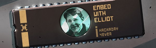
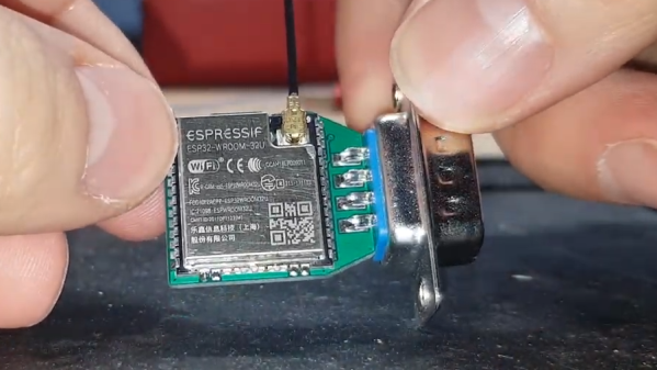
The adapter features an ESP32 and is attached to a DB-9 plug, so it’s nice and small. It uses the ST3232 chip to communicate at 3 V logic levels on the microcontroller side, supports bipolar logic up to +/-13 V on the vintage hardware side, and a rudimentary web interface allows setting hardware parameters like baud rate. The nice thing about the ST3232 transceiver is that it is not only small, but can work from a 3 V supply with only four 0.1 uF capacitors needed for the internal charge pumps.

As for actually using the adapter, [g3gg0] says that the adapter’s serial port is exposed over TCP on port 23 (Telnet) which is supported by some programs and hardware. Alternately, one can connect an ESP32 to one’s computer over USB, and run firmware that bridges any serial data directly to the adapter on the other end.

Design files including schematic, bill of materials, and PCB design are shared online, and you can see a brief tour of the adapter in the video, embedded below.

Continue reading “DIY Wireless Serial Adapter Speaks (True) RS-232”

Hackaday Podcast 004: Taking The Blue Pill, Abusing Resistors, And Not Finding Drones

Catch up on your Hackaday with this week’s podcast. Mike and Elliot riff on the Bluepill (ST32F103 boards), blackest of black paints, hand-crafted sorting machines, a 3D printer bed leveling system that abuses some 2512 resistors, how cyborgs are going mainstream, and the need for more evidence around airport drone sightings.

Stream or download Episode 4 here, and subscribe to Hackaday on your favorite podcasting platform! You’ll find show notes after the break.

Take a look at the links below if you want to follow along, and as always, tell us what you think about this episode in the comments!

Direct download (60 MB or so.)

Continue reading “Hackaday Podcast 004: Taking The Blue Pill, Abusing Resistors, And Not Finding Drones”

Analog Clock Goes Digital, Or Vice Versa

Designing a good clock takes a lot of considerations. It’s not just hands, faces, and numbers anymore; there are also word clocks, electronic clocks, marble clocks, or water clocks, and just about anything else imaginable can be used to tell time. Of course, electronic clocks are great for their versatility, and this one shows off an analog-looking clock that is (of course) digital, leveraging all of the perks of analog with all of the upsides of digital electronics.

One of the key design considerations that [Sasa] had while building this piece was that it needed to be silent. LEDs certainly fit that description, so the decision was made to go with an WS2812b ring. It runs using a STM ST32F103 Nucleo board (and a cheaper version of it in later versions of this clock) which shows a red LED for the current hour, yellow LEDs for the traditional analog clock divisions, a green LED for the current minute, and glows the rest of the LEDs up to the current minute with a rainbow pattern.

This is a really clean, simple build with good design at its core, and would be easy to replicate if you’re looking for an eye-catching clock to build. As a bonus, all of the schematics and code are available on the project site, so everything you need is there. If you’re looking for more inspiration, there are some clocks that are even more unique, like this marble clock that is a work of art — but is anything but silent.

Astro Cat: Raspberry Pi Telescope Controller

When somebody tackles an engineering problem, there are two possible paths: they can throw together a quick and dirty fix that fits their needs (the classic “hack”, as it were), or they can go the extra mile to develop a well documented solution that helps the community as a whole. We cover it all here at Hackaday, but we’ve certainly got a soft spot for the latter approach, even if some may feel it falls into the dreaded territory of “Not A Hack”.

When [Gary Preston] wanted to control his telescope and astrophotography hardware, he took the second path in a big way. Over the course of several posts on his blog, [Gary] walks us though the creation of his open source Raspberry Pi add-on board that controls a laundry list of sensors and optical gear. Just don’t call it a HAT, while it may look the part, [Gary] is very specific that it does not officially meet the HAT specifications put out by the Raspberry Pi Foundation.

Even if you aren’t terribly interested in peering into the infinite void above, the extremely detailed write-up [Gary] has done contains tons of multidisciplinary information that you may find useful. From showing how to modify the Pi’s boot configuration to enable true hardware UART (by default, the Pi 3 ties it up with Bluetooth) and level shifting it with a ST3232 to a breakdown of the mistakes he made in his PCB layout, there’s plenty to learn.

Astro CAT is a completely open source project, with the hardware side released under the CERN Open Hardware License v1.2, and the INDI driver component is available under the GPL v3.

If this looks a bit daunting for your first stab at astrophotography with the Raspberry Pi, fear not. We’ve covered builds which can get you up and running no matter what your budget or experience level is.

A Few Of Our Favorite Chips: 4051 Analog Mux

Raindrops on roses, and whiskers on kittens? They’re alright, I suppose. But when it comes down to it, I’d probably rather have a bunch of 4051, 4052, and 4053 analog multiplexers on the component shelf. Why? Because the ability to switch analog signals around, routing them at will, under control of a microcontroller is tremendously powerful.

Whether you want to read a capacitive-sensing keyboard or just switch among audio signals, nothing beats a mux! Read on and see if you agree.

Continue reading “A Few Of Our Favorite Chips: 4051 Analog Mux”

Embed With Elliot: Microcontroller Makefiles

Last time on Embed with Elliot, I began my celebration of the make command’s 40th birthday next month. We discussed using the default rules and how to augment them with your own variables defined in a makefile. Next, I’ll walk you through some makefiles that can be used for real-world microcontroller code development. This week, we’ll focus on one for the AVR platform, and later on, I’ll run through a slightly more complicated version for the ST32M series of ARM Cortex micros.

Along the way, we’ll pick up a couple of tricks, but the aim is to keep the makefiles minimal, readable, and easily extensible. Once you get a little taste of the power of writing your own makefiles, you probably won’t be able to stop adding bells and whistles — custom routines for flashing, checking the size of binaries, generating assembly listings, etc. I’ll leave the extras up to you, but you’ll eventually find that anything you do can be automated with a makefile.

Continue reading “Embed With Elliot: Microcontroller Makefiles”

STM32 Driving A PCIe Video Card

[Gpuhackr] chose his username to explain exactly how he spends his time. For instance, here he’s using an STM32 Discovery board to drive an AMD Radeon HD 2400 graphics card. The ARM microcontroller isn’t actually using the PCIe interface on the card. Instead, [Gpuhackr] has patched into the debugging interface built into the card itself. This isn’t quite as straight forward as it sounds, but if you do the wiring carefully it’s a pretty intersting way to connect an ARM to an LCD monitor.

This project would be almost impossible if it weren’t for the open source code which AMD has released. This lets him implement the card’s 3D rendering features. The demo directly programs the UVD Xtensa CPU which is on the video card. It draws a cube with color gradients on each side. The cube spins while the debug information is overlaid on the screen. In this case the ARM chip/board is really being used as a programmer to upload some custom firmware. But we think a real code-ninja could implement a communications protocol to open up a simple way to drive the card in real-time.

[Thanks uMinded]