Coffee Alarm

Alarm Notifies The Office When The Coffee Is Ready

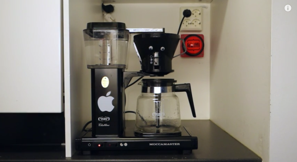
[Stian] thought it would be nice if his coworkers could be electronically notified when the latest batch of coffee is ready. He ended up building an inexpensive coffee alarm system to do exactly that. When the coffee is done, the brewer can press a giant button to notify the rest of the office that it’s time for a cuppa joe.

[Stian’s] first project requirement was to activate the system using a big physical button. He chose a button from Sparkfun, although he ended up modifying it to better suit his needs. The original button came with a single LED built-in. This wasn’t enough for [Stian], so he added two more LEDs. All three LEDs are driven by a ULN2003A NPN transistor array. Now he can flash them in sequence to make a simple animation.

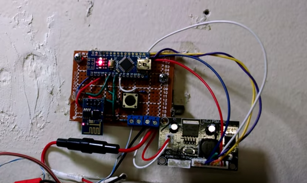
This momentary push button supplies power to a ESP8266 microcontroller using a soft latch power switch. When the momentary switch is pressed, it supplies power to the latch. The latch then powers up the main circuit and continues supplying power even when the push button is released. The reason for this power trickery is to conserve power from the 18650 li-on battery.

The core functionality of the alarm uses a combination of physical hardware and two cloud-based services. The ESP8266 was chosen because it includes a built-in WiFi chip and it only costs five dollars. The microcontroller is configured to connect to the WiFi network with the push of a button. The device also monitors the giant alarm button.

When the button is pressed, it sends an HTTP request to a custom clojure app running on a cloud service called Heroku. The clojure app then stores brewing information in a database and sends a notification to the Slack cloud service. Slack is a sort of project management app that allows multiple users to work on projects and communicate easier over the internet. [Stian] has tapped into it in order to send the actual text notification to his coworkers to let them know that the coffee is ready. Be sure to watch the demo video below. Continue reading “Alarm Notifies The Office When The Coffee Is Ready”

AlarmLamp

Prefix Your Phone Alarm With A Desk Lamp

If you are like [Gbola], then you have a hard time waking up during the winter months. Something about the fact that it’s still dark outside just makes it that much more difficult to get out of bed. [Gbola] decided to build his own solution to this problem, by gradually waking himself up with an electric light. He was able to do this using all off-the-shelf components and a bit of playing around with the Tasker Android application.

[Gbola] started out with a standard desk lamp. He replaced the light bulb with a larger bulb that simulates the color temperature of natural daylight. He then switched the lamp on and plugged it into a WeMo power switch module. A WeMo is a commercial product that attempts to make home automation accessible for consumers. This particular module allows [Gbola] to control the power to his desk lamp using his smart phone.

[Gbola] mentions that the official WeMo Android application is slow and includes no integration with Tasker. He instead decided to use the third-party WeMoWay application, which does include Tasker support. Tasker is a separate Android application that allows you to configure your device to perform a set task or series of tasks based on a context. For example you might turn your phone to silent mode when your GPS signal shows you are at work. WeMoWay allows [Gbola] to interact with his WeMo device based on any parameter he configures.

On top of all of that, [Gbola] also had to install three Tasker plugins. These were AutoAlarm, Taskkill, and WiFi Connect. He then got to work with Tasker. He configured a custom task to identify when the next alarm was configured on the phone. It then sets two custom variables, one for 20 minutes before the alarm (turn on the lamp) and one for 10 minutes after (turn it off).

[Gbola] then built a second task to actually control the lamp. This task first disconnects and reconnects to the WiFi network. [Gbola] found that the WeMoWay application is buggy and this “WiFi reset” helps to make it more reliable. It then kills the WeMoWay app and restarts it. Finally, it executes the command to toggle the state of the lamp. The project page has detailed instructions in case anyone wants to duplicate this. It seems like a relatively painless way to build your own solution for less than the cost of a specialized alarm clock lamp.

BagAlarm

Motion Activated Alarm For Your Bag

Many of us carry around a bag with our expensive personal belongings. It can be a pain to carry a bag around with you all day though. If you want to set it down for a while, you often have to try to keep an eye on it to ensure that no one steals it. [Micamelnyk] decided to build a solution to this problem in the form of a motion sensing alarm.

The device is built around a Trinket Pro. The Trinket Pro is a sort of break out board for the ATMega328. It’s compatible with the Arduino IDE and also contains a USB port for easy programming. The Trinket is hooked up to a GY-521 accelerometer, which allows it to detect motion. When the Trinket senses that the device has been moved, it emits a loud high-pitched whine from a piezo speaker.

To arm the device, the user first holds the power button for 3 seconds. Then the user has ten seconds to enter their secret code. This ensures that the device is never armed accidentally and that the user always remembers the code before arming the device. The code is entered via four push buttons mounted to a PCB. The code and code length can both be easily modified in the Trinket software.

Once the code is entered, the status LED will turn solid. This indicates to the user that the device must be placed stationary. The LED will turn off after 20 seconds, indicating that the alarm is now armed. If the bag is moved for more than five seconds at a time, the alarm will sound. The slight delay gives the user just enough time to disarm the alarm. This parameter can also be easily configured via software.

Alarm1

Adding WiFi And SMS To An Alarm System

[Don] wanted to bring his alarm system into the modern age. He figured that making it more connected would do the trick. Specifically, he wanted his alarm system to send him an SMS message whenever the alarm was tripped.

[Don] first had to figure out a way to trigger an event when the alarm sounds. He found a screw terminal that lead to the siren. When the alarm is tripped, this screw terminal outputs 12V to enable the siren. This would be a good place to monitor for an alarm trip.

[Don] is using an Arduino nano to monitor the alarm signal. This meant that the 12V signal needed to be stepped down. He ran it through a resistor and a Zener diode to lower the voltage to something the Arduino can handle. Once the Arduino detects a signal, it uses an ESP8266 WiFi module to send an email. The address [Don] used is the email-to-SMS address which results in a text message hitting his phone over the cell network.

The Arduino also needed power. [Don] found a screw terminal on the alarm system circuit board that provided a regulated 12V output. He ran this to another power regulator board to lower the voltage to a steady 5V. This provides just the amount of juice the Arduino needs to run, and it doesn’t rely on batteries. [Don] provides a good explanation of the system in the video below. Continue reading “Adding WiFi And SMS To An Alarm System”

Arduino-Powered Alarm System Has All The Bells And Whistles

Put aside all of the projects that use an Arduino to blink a few LEDs or drive one servo motor. [IngGaro]’s latest project uses the full range of features available in this versatile microcontroller and has turned an Arduino Mega into a fully-functional home alarm system.

The alarm can read RFID cards for activation and control of the device. It communicates with the front panel via an I2C bus, and it can control the opening and closing of windows or blinds. There is also an integrated GSM antenna for communicating any emergencies over the cell network. The device also keeps track of temperature and humidity.

The entire system can be controlled via a web interface. The Arduino serves a web page that allows the user full control over the alarm. With all of that, it’s hard to think of any more functionality to get out of this tiny microcontroller, unless you wanted to add a frickin’ laser to REALLY trip up the burglars!

5 Digit Security Code Activated Relay Using Mostly Discrete Circuitry

alarm keypad

Let’s rollback the hobby electronics calendar a few decades with [myvideoisonutube’s] alarm activation control circuit using a matrix style phone keypad. The circuit is quite old using CMOS 4081 with 4 ‘AND’ gates to hardwire the access code. [myvideoisonutube] references [Ron’s] “Enhanced 5-Digit Alarm Keypad” schematic for this build changing the recommend keypad with a more common matrix style keypad found in touch pad phones. These types of matrix keypads wouldn’t work outright for the input so he cut some traces and added hookup wires to transform it into a keypad with common terminals and separately connected keys. We love seeing such hacked donor hardware even when it requires extensive modifications. [Ron’s] source circuit included a simple enough to build tactical button keypad if you can’t find a suitable donor phone.

Learning how to use mostly discrete components instead of a microcontroller would be the core objective to build this circuit outside of needing a key-code access point or other secure 12 V relay activated device. Such a device would be quite secure requiring a 4 digit “on” code and 5 digits for “off”. You couldn’t just pull off the keypad and hotwire or short something to gain access either. The 4 digit on “feature” does knock the security down quite a lot. However, all keys not in the access code are connected to the same point so you could increase your security by using a pad with more keys.

On [Ron’s] site you will find a detailed construction guide including top and bottom view for placement of all the components on veroboard. Join us after the break to watch [myvideoisonutube] demo his version.

Continue reading “5 Digit Security Code Activated Relay Using Mostly Discrete Circuitry”

Cloning An Infrared Disarming Remote Of A $8 Home Security System

5

[Sylvio] decided to buy one of the cheap alarm systems you can find on the internet to have a look at its insides. The kit he bought was composed of one main motion sensor and two remote controls to arm/disarm it.

Communication between the remotes and the sensor is done by using infrared, requiring a direct line of sight for a signal to be received. Modern alarm systems typically use RF remotes with a typical frequency of 434MHz or 868MHz.  In his write-up, [Sylvio] first tries to replicate the IR signal with one of his ‘learning remote controls’ without success and then proceed to reverse engineering the remote circuit shown in the above picture. Hackaday readers may figure out just by looking at it that it is a simple astable multivibrator (read ‘oscillator’). Its main frequency is 38.5kHz, which is typical for IR applications. Therefore, if one of your neighbours had this ‘security system’ one could just disarm it with any of the same remotes…

[Sylvio] then explains different ways to replicate the simple IR signal, first with an Arduino then with a frequency generator and finally using the USB Infrared Toy from Dangerous Prototypes. We agree with his conclusion: “you get what you pay for”.