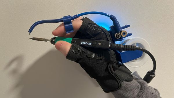
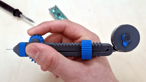
JBC soldering station sitting atop a custom switch box next to a selection of hot ends.

A 3-tool Selector Box For A JBC Soldering Station

Soldering is one of those jobs that are conceptually simple enough, but there’s quite a bit of devil in the detail and having precisely the right tool for the job in hand is essential for speed and quality of results. The higher-quality soldering stations have many options for the hot end, but switching from a simple pencil to hot tweezers often means unplugging one and reattaching the other, and hoping the station recognises the change and does the right thing. [Lajt] had three soldering options and a single output station. Their solution was a custom-built three-way frontend box that provides a push-button selection of the tool to be connected to the station sitting atop.

[Lajt] shows in the blog post how each of their target hot ends is wired and the connectivity the control station expects to determine what is plugged in. Failing to recognise a connected 50 W heating element as if the smaller 25 W unit was still connected would suck, with a huge amount of lag as the temperature of the hot end would fail to keep up with the thermal load during use. When connections are made, it is important to ensure the unit has sufficient time to detect the change in output and configure itself appropriately. An Arduino Pro mini handles the selection between outputs by driving a selection of relays with appropriate timing. An interesting detail here is what [Lajt] calls a ‘sacrificial relay’ in the common ground path, which has a greater contact rating than the others and acts as a secondary switch to save wear on the other relay contacts that would otherwise be hot-switched. All in all, a nicely executed project, which should offer years of service.

We like DIY tools and tool-related hacks. Here’s a DIY Hakko station, a Weller clone unit, and a peek inside TS1C portable unit.

Continue reading “A 3-tool Selector Box For A JBC Soldering Station”

Mapping The Nintendo Switch PCB

As electronics have advanced, they’ve not only gotten more powerful but smaller as well. This size is great for portability and speed but can make things like repair more inaccessible to those of us with only a simple soldering iron. Even simply figuring out what modern PCBs do is beyond most of our abilities due to the shrinking sizes. Thankfully, however, [μSoldering] has spent their career around state-of-the-art soldering equipment working on intricate PCBs with tiny surface-mount components and was just the person to document a complete netlist of the Nintendo Switch through meticulous testing, a special camera, and the use of a lot of very small wires.

The first part of reverse-engineering the Switch is to generate images of the PCBs. These images are taken at an astonishing 6,000 PPI and as a result are incredibly large files. But with that level of detail the process starts to come together. A special piece of software is used from there that allows point-and-click on the images to start to piece the puzzle together, and with an idea of where everything goes the build moves into the physical world.

[μSoldering] removes all of the parts on the PCBs with hot air and then meticulously wires them back up using a custom PCB that allows each connection to be wired up and checked one-by-one. With everything working the way it is meant to, a completed netlist documenting every single connection on the Switch hardware can finally be assembled.

The final documentation includes over two thousand photos and almost as many individual wires with over 30,000 solder joints. It’s an impressive body of work that [μSoldering] hopes will help others working with this hardware while at the same time keeping their specialized skills up-to-date. We also have fairly extensive documentation about some of the Switch’s on-board chips as well, further expanding our body of knowledge on how these gaming consoles work and how they’re put together.

Lift Those Pins With Ease

Reworking is one of the regular tasks of anyone who is involved in an electronic design process, because try as we might, it’s rare to get a design perfectly right the first time. Some reworking tasks are more difficult than others though, and we have to admit that lifting an IC pin doesn’t always result in success. But with this video from [Mr. SolderFix] there’s hope for conquering the technique, as he takes us through the best pin-raising technique on a variety of packages.

The trick it seems is to lift the pin first without attempting to disengage it from the molten solder, then returning to it with some copper braid to remove the solder and leave it raised. Once the secret is revealed it’s so easy, something a Hackaday scribe should be able to do. He does sound a note of caution though, as some packages are prone to disintegrating when stressed. A broken SOT-23 is not something anyone likes to see through their magnifier.

His channel is full of such no-nonsense soldering advice, and should be a fascinating browse for many readers. Meanwhile we’ve covered quite a bit of rework technique ourselves, such as last year when we looked at BGA work.

Continue reading “Lift Those Pins With Ease”

Check Out These Amazing Self-Soldering Sleeves From World War II

Imagine you’re a commando, doing some big secret mission on the continent in the midst of World War II. You need to hook up some wires to your explosive charges, and time is of the essence. Do you bust out the trusty Weller and see if those petulant Axis chaps will let you plug it in somewhere? No! You use a pyrotechnic self-soldering sleeve, as [Our Own Devices] explains.

Like so many British inventions during the war, the sleeves really are ingenious. They were developed by the Special Operation Executive, an organization charged with sabotage and subversion operations in then-occupied Europe.

The soldering sleeves were designed to make electrical connections between detonators and firing wires for explosives.  The sleeves consist of a copper tube through which wires to be joined are fed, with a lump of solder in the middle. The assembly is covered in pyrotechnic material with a safety match-style starter chemical dosed on top. Using the sleeves is simple. First, two stripped wires are fed into either end of the copper tube. The starter the sleeve is then ignited using the box, just like striking a match. The pyrotechnic material then gets red hot, melting the solder and making the connection.

It’s well worth watching the video to see how these field-expedient devices actually work. We’ve explored the use of more-typical solder sleeves before, too. Video after the break.

Continue reading “Check Out These Amazing Self-Soldering Sleeves From World War II”

Flux, From Scratch

Soldering flux is (or at least, should be) one of the ubiquitous features of any electronics bench. It serves the purpose of excluding oxygen from a solder joint as it solidifies, and in most cases its base is derived from pine rosin. Most of us just buy flux, but [pileofstuff] is having a go at making his own.

He starts with a block of rosin and a couple of different solvents. Isopropanol we’re happy with, but perhaps using methanol for something to be vaporized within breathing distance isn’t something we’d do. At about 25% rosin to solvent ratio the result is a yellow liquid flux, which he tests against some commercial fluxes. The result is a reasonable liquid flux, something which perhaps shouldn’t be too much of a surprise, and is a handy piece of information to store away should we ever be MacGuyver-like stuck in a pine forest with a need to save the day with electronics.

It would be interesting to try the same technique but with a solvent selected to soften the rosin for a paste flux, and perhaps any chemists among our readership could enlighten us about just what rosin is beside the heavy fractions left after extracting the volatiles from pine resin.

In the past we’ve taken a close look at how solder really works.

Continue reading “Flux, From Scratch”

CNC Soldering Bot Handles Your Headers

Soldering pin headers by hand is a tedious task, especially when your project has a huge number of them. [iforce2d] has a large number of boards with a lot of headers, and has created a rather special CNC machine to to do the job. It’s a soldering robot, controlled by LinuxCNC and you can see it below the break.

Superficially it resembles a 3D printer made in aluminium, with an X-Y movable table and a Z-direction represented by a soldering iron and solder feeder on an arm. The solder feeder uses a Bowden tube, with a 3D-printer extruder motor pushing the solder wire down a PTFE tube and finally into a fine aluminium tube from which it’s fed to the iron tip.

Though he’s done a beautiful job of it, creating the machine is not all that’s required, because the tool path requires more attention than simply moving the iron to each pin and supplying some solder. There’s a need to consider the effect of that heat, how much each pad needs, and how much neighbouring pads contribute.

We’ve had repetitive soldering tasks just like this one though not on this scale, so we can understand the tedium this machine will relieve. We can’t however help being reminded of XKCD 1319.

Continue reading “CNC Soldering Bot Handles Your Headers”

Hackaday Prize 2023: One-Handed Soldering With The Solder Sustainer

For a lot of us, soldering has become so ingrained that it’s muscle memory. We know exactly when the iron is hot enough, how long to leave the tip in contact with the joint to heat it up, and exactly where to dab in the solder to get it to flow. When you’re well-practiced it can be a beautiful thing, but for those who don’t do it frequently, soldering can be frustrating indeed.

The “Solder Sustainer” looks like it just might be aimed at solving that problem, as well as a few others. It comes to us from [RoboticWorx], and while it looks a little like the love child of a MIG welder and a tattoo machine, it’s got a lot going for it. The idea is to make soldering a one-handed task by combining the soldering iron and a solder wire feeder into one compact package. The solder feeder is very reminiscent of a filament extruder on a 3D printer, using a stepper to drive spring-loaded pinch wheels, which forces the solder down a curved 3D-printed tube that directs it toward the tip. The pancake stepper is driven by an ESP32, which also supports the touch sensor that lets you advance the solder. The whole thing can be powered off a USB-C power supply, or using the onboard USB charger that can be connected in line with the soldering iron supply.

The video below shows Solder Sustainer in use. Yes, we know — some of those joints look a little iffy. But that seems to have more to do with technique than with the automatic solder feed. And really, in situations where you’ve previously wished for a third hand while soldering, this would probably be just the thing.

The Solder Sustainer is an entry in the “Gearing Up” round of the 2023 Hackaday Prize. If you’ve got an idea for a tool, jig, fixture, or instrument that makes hacking easier, we want to know about it. But you’d better hurry — the round ends on August 8.

Continue reading “Hackaday Prize 2023: One-Handed Soldering With The Solder Sustainer”