Don’t Fear The Filter: Lowpass Edition

There comes a time in every electronic designer’s life when, whether they know it or not, they need an analog filter in their design. If you’re coming from a digital background, where everything is nice and numeric, the harsh reality of continuous voltages can be a bit of a shock. But if you’re taking input from, or sending output to the big analog world out there, it pays to at least think about the frequency-domain properties of the signal, and maybe even do something about them.

Designing an analog filter to fit your needs can be a bit of a daunting task: there are many factors that you’re going to need to consider, and they all interact. It’s easy to get lost. We’re going to simplify this as much as possible by instead focusing on a few common applications and building up the simplest possible filters that work well for them.

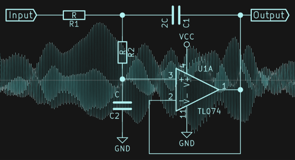
Today, we’re going to consider the lowpass filter, and specifically a Sallen-Key filter with Butterworth characteristics and a second-order rolloff. Sound like word salad? We’ll fix that up right away, because this is probably the single most important filter to have in your analog toolbox for two very common use cases: pulse-width modulated (PWM) output and analog-to-digital conversion (ADC) input.

Continue reading “Don’t Fear The Filter: Lowpass Edition”

Paul: A Robot And Its Ball

[Jochen Alt]’s Paul is one of the coolest robots of its type, and maybe one of the coolest robots period. Personality? Check. Omniwheels? Check. Gratuitous feats of derring-do? Check. Paul is a ball balancing robot.

Under the hood, Paul isn’t all that strange. He’s got two microcontrollers, one for taking care of the balancing and kinematics, and another that handles the LEDs, speech processor, loudspeaker, remote-control, and other frilly bits. But the mathematics! Paul is a cylinder standing up on top of a bowling ball, so the only way it can roll forwards is to lean forwards. But of course, it can’t lean too much, because it has also got to balance. It’s absolutely the least reasonable means of locomotion. We love it.

[Jochen] was nice enough to put everything up on GitHub, so you can see how it was done, even though it looks like magic. And we dare you to watch the video, embedded below, and not feel at least a pang of sympathy pain when (spoiler alert!) he falls flat on his face. Does he recover? We’d love to know!

Paul is just one of the stellar robots in the 2017 Hackaday Sci-Fi contest, so head on over there if you still don’t have your fill.

Continue reading “Paul: A Robot And Its Ball”

Another Day, Another “IoT” Backdoor

As if you needed any reason other than “just for the heck of it” to hack into a gadget that you own, it looks like nearly all of the GSM-to-IP bridge devices make by DBLTek have a remotely accessible “secret” backdoor account built in. We got sent the link via Slashdot which in turn linked to this story on Techradar. Both include the scare-words “Chinese” and “IoT”, although the devices seem to be aimed at small businesses, but everything’s “IoT” these days, right?

What is scary, however, is that the backdoor isn’t just a sloppy debug account left in, but rather only accessible through an elaborate and custom login protocol. Worse still, when the company was contacted about the backdoor account, they “fixed” the problem not by removing the account, but by making the “secret” login procedure a few steps more complicated. Which is to say, they haven’t fixed the problem at all.

This issue was picked up by security firm Trustwave, but they can’t check out every device on the market all the time. We may be preaching to the choir here, but if you’re ever wondering why it’s important to be able to break into stuff that you own, here’s another reminder.

What Voltage For The All-DC House?

The war of the currents was fairly decisively won by AC. After all, whether you’ve got 110 V or 230 V coming out of your wall sockets, 50 Hz or 60 Hz, the whole world agrees that the frequency of oscillation should be strictly greater than zero. Technically, AC won out because of three intertwined facts. It was more economical to have a few big power plants rather than hundreds of thousands of tiny ones. This meant that power had to be transmitted over relatively long distances, which calls for higher voltages. And at the time, the AC transformer was the only way viable to step up and down voltages.

acdc
No, not that AC/DC

But that was then. We’re right now on the cusp of a power-generation revolution, at least if you believe the solar energy aficionados. And this means two things: local power that’s originally generated as DC. And that completely undoes two of the three factors in AC’s favor. (And efficient DC-DC converters kill the transformer.) No, we don’t think that there’s going to be a switch overnight, but we wouldn’t be surprised if it became more and more common to have two home electrical systems — one remote high-voltage AC provided by the utilities, and one locally generated low-voltage DC.

Why? Because most devices these days use low-voltage DC, with the notable exception of some big appliances. Batteries store DC. If more and more homes have some local DC generation capability, it stops making sense to convert the local DC to AC just to plug in a wall wart and convert it back to DC again. Hackaday’s [Jenny List] sidestepped a lot of this setup and went straight for the punchline in her article “Where’s my low-voltage DC wall socket?” and proposed a few solutions for the physical interconnects. But we’d like to back it up for a minute. When the low-voltage DC revolution comes, what voltage is it going to be?

Continue reading “What Voltage For The All-DC House?”

A Command-Line Stepper Library With All The Frills

When you already know exactly where and how you’d like your motor to behave, a code-compile-flash-run-debug cycle can work just fine. But if you want to play around with a stepper motor, there’s nothing like a live interface. [BrendaEM]’s RDL is a generic stepper motor driver environment that you can flash into an Arduino. RDL talks to your computer or cell phone over serial, and can command a stepper-driver IC to move the motor in three modes: rotary, divisions of a circle, and linear. (Hence the acronumical name.) Best of all, the entire system is interactive. Have a peek at the video below.

The software has quite a range of capabilities. Typing “?” gets you a list of commands, typing “@” tells you where the motor thinks it is, and “h” moves the motor back to its home position. Rotating by turns, degrees, or to a particular position are simple. It can also read from an analog joystick, which will control the rotation speed forward and backward in real time.

Division mode carves the pie up into a number of slices, and the motor spins to these particular locations. Twelve, or sixty, divisions gives you a clock, for instance. Acceleration and deceleration profiles are built in, but tweakable. You can change microstepping on the fly, and tweak many parameters of the drive, and then save all of the results to EEPROM. If you’re playing around with a new motor, and don’t know how quickly it can accelerate, or what speeds it’s capable of, nothing beats playing around with it interactively.

Continue reading “A Command-Line Stepper Library With All The Frills”

Reading The Unreadable SROM: Inside The PSoC4

Wow. [Dmitry Grinberg] just broke into the SROM on Cypress’ PSoC 4 chips. The supervisory read-only memory (SROM) in question is a region of proprietary code that runs when the chip starts up, and in privileged mode. It’s exactly the kind of black box that’s a little bit creepy and a horribly useful target for hackers if the black box can be broken open. What’s inside? In the manual it says “The user has no access to read or modify the SROM code.” Nobody outside of Cypress knows. Until now.

This matters because the PSoC 4000 chips are among the cheapest ARM Cortex-M0 parts out there. Consequently they’re inside countless consumer devices. Among [Dmitry]’s other tricks, he’s figured out how to write into the SROM, which opens the door for creating an undetectable rootkit on the chip that runs out of each reset. That’s the scary part.

The cool parts are scattered throughout [Dmitry]’s long and detailed writeup. He also found that the chips that have 8 K of flash actually have 16 K, and access to the rest of the memory is enabled by setting a single bit. This works because flash is written using routines that live in SROM, rather than the usual hardware-level write-to-register-and-wait procedure that we’re accustomed to with other micros. Of course, because it’s all done in software, you can brick the flash too by writing the wrong checksums. [Dmitry] did that twice. Good thing the chips are inexpensive.

The nitty-gritty on the ROP (return oriented programming) tricks that [Dmitry] had to pull, and a good look into the design of the system itself, are all up on [Dmitry]’s blog. We can’t wait to see what other buried treasure he’s going to find as he continues to play around with these chips. And in case you’re wondering what type of mad genius it takes to pull this off, consider that [Dmitry] runs Linux on AVRs, fools nRF24 chips into transmitting Bluetooth LE beacons, and re-writes his own airplane’s GPS.

[Main image is a PSoC4200 dev kit, and [Dmitry] has only been working with the 4000 and 4100 series. Just so you know.]

Glitchy Synthesizer Meets Honeycomb LED Matrix

Don’t watch [Jason Hotchkiss]’s video if flashing lights or bleepy-bloopy synthesizer noises give you seizures. Do watch, however, if you’re interested in a big honeycomb-shaped LED matrix being driven at audio frequencies through a dedicated square-wave synthesizer that’s built in.

The LED panel in question is housed in a snazzy laser-cut, honeycomb-shaped bezel: a nice change from the standard square in our opinion. The lights are 1/2 watt (whoa!) whites, and the rows and columns are driven by transistor drivers that are in turn controlled by shift registers. We’re not entirely sure how the matrix is driven — we’d love to see a circuit diagram — but it looks like it’s some kind of strange, non-scanning mode where all of the column and row drives are on at once. Whatever, it’s art.

And it’s driven by logic chips making audio-frequency square waves. Two of these are fed into an LFSR and into an R-2R DAC and then into the shift registers. The output is chaos, but the audio and the visuals do seem to influence each other. It’s an audio-visual embodiment of some of my wildest Logic Noise fantasies. Pretty cool. Enjoy the video.

Continue reading “Glitchy Synthesizer Meets Honeycomb LED Matrix”