Making Custom 3D Printed Slide Switches

For a little over a year now we’ve been covering the incredible replicas [Mike Gardi] has been building of educational “computers” from the very dawn of the digital age. These fascinating toys, many of which are now extremely rare, are recreated using 3D printing and other modern techniques for a whole new generation to enjoy and learn from.

He’s picked up a trick or two building these replicas, such as this method for creating bespoke slide switches with a 3D printer. Not only does this idea allow you to control a custom number of devices, but as evidenced in the video after the break, the printed slider sounds absolutely phenomenal in action. Precisely the sort of “clunk” you want on your front panel.

Of course, [Mike] doesn’t expect anyone to create this exact switch. He’s designed it as part of his Working Digital Computer (WDC-1) project that he’s documenting on Hackaday.io, so it has a rather specific set of design parameters. But with the steps he outlines in the write-up, you should have no problem adapting the concept to fit your specific needs.

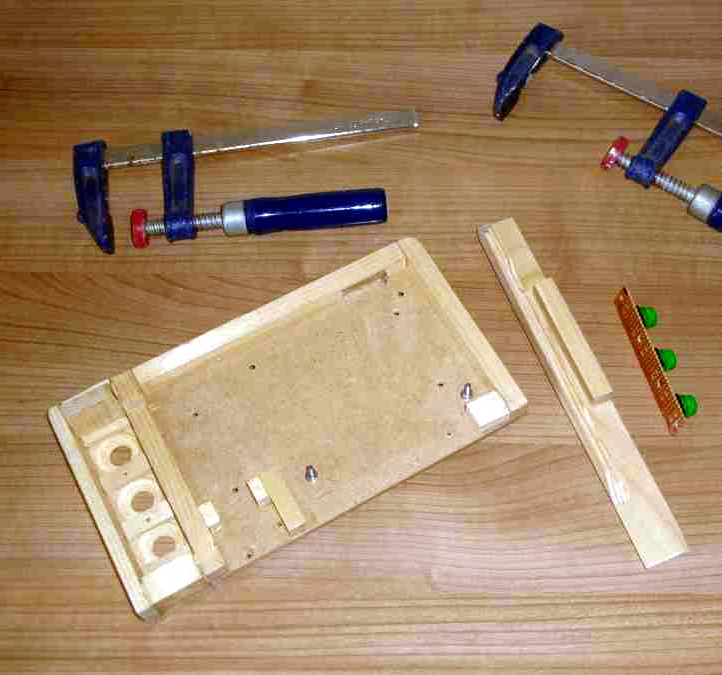
So how does it work? One half of the switch is a track is printed with indents for both reed switches and 6 x 3 mm disc magnets. The other is a small shuttle that itself has spaces for two of the same magnets. When it slides over the reed switches they’re activated by the magnet on one side, while the magnet on the other side will be attracted to the one embedded into the track. This not only gives the switch detents that you can feel and hear while moving it, but keeps the shuttle from sliding off the intended reed switch.

If you like this, you’ll absolutely love his mostly 3D printed binary encoder that we featured recently. With his track record, we’re excited to follow the WDC-1 project as it develops, and thrilled that [Mike] has brought it to Hackaday.io.

Continue reading “Making Custom 3D Printed Slide Switches”

An ESP8266 Environmental Monitor In Your USB Port

At this point, we’ve all seen enough ESP8266 “weather stations” to know the drill: you just put the ESP and a temperature sensor inside a 3D printed case, and let all those glorious Internet Points™ flow right on in. It’s a simple, and perhaps more importantly practical, project that seems to never get old. But that doesn’t mean there isn’t room for innovation.

Annoyed by the unnecessary bulk of existing solutions, [cperiod] has come up with an ESP8266 temperature and humidity sensor that can plug directly into a standard USB port. Slotted into a USB wall charger or power bank, this diminutive board can provide inconspicuous remote environmental monitoring wherever you need it. For extra hacker points, the board was even produced at home on a PCB mill.

In addition to the ESP-7 or 12 module (which plugs in via a header, should you need to swap it out), the board features a CH330N USB to UART chip and HT7233 voltage regulator. For the sensor itself, [cperiod] has bucked convention a bit and went with the I2C-connected AHT10 over something more common like a member of the BME family.

Unfortunately, this design suffers from the same issue we’ve seen in other compact environmental monitoring solutions; namely, that the heat generated by the chip itself skews the temperature readings. To combat this, aggressive power saving functions are baked into the firmware to make sure the ESP is in a deep sleep as much as possible. While not a perfect solution, it does prevent the ESP from warming the PCB up so much that it invalidades the reported data.

By now, the particularly astute reader may have realized that all the additional components used for the USB side of this board aren’t strictly necessary. After all, if you can pull the ESP module out of the header and program it separately, then you don’t actually need to include that capability in each sensor node. While true, we’re hardly the ones to complain when a hacker showboats a bit on their designs.

Poking Around Inside A Pair Of Classic Gaming Gifts

Retro gaming is huge right now, and like probably millions of other people, [wrongbaud] found himself taking possession of a couple faux-classic gaming gadgets over the holidays. But unlike most people, who are now using said devices to replay games from their youth, he decided to tear into his new toys to see how they work.

The first to get pulled apart is a handheld The Oregon Trail game, which Hackaday readers may recall from a teardown we did back when it was first released. His work continues right where our teardown left off, by pulling the game’s two EEPROM chips out and dumping their contents. As expected, [wrongbaud] found that the I2C connected chip contained the game save information, and the SPI flash chip stored the actual game files.

Next up was an HDMI “stick” from Bandai Namco that allows the user to play a selection of NES games. Here again [wrongbaud] liberates the flash chip and dumps it for examination, this time using an ESP32 tool of his own creation. Inside the firmware image he’s able to identify several elements with the help of binwalk, such as splash screen graphics and text strings.

But perhaps most interestingly, he found that binwalk was able to automatically extract the NES ROMs themselves. After verifying they were standard ROMs with an NES emulator, he theorizes that repacking the firmware with different ROMs should be possible should anyone feel so inclined.

Both of these hacks are fantastic examples of how you can reverse engineer a device’s firmware with low cost hardware, open source tools, and a healthy dose of patience. Even if you aren’t interested in fiddling with The Oregon Trail or swapping out the Mappy ROM for Contra, this write-up is an invaluable resource for anyone looking to do their own firmware analysis.

This isn’t the first time [wrongbaud] has hacked around inside these extremely popular retro games, either. Just last month we covered some of his previous exploits with the re-released versions of Rampage and Mortal Kombat.

A Homebrew Weller RT Soldering Station

Like a number of hackers before him, [MarcelMG] was impressed with Weller’s RT soldering iron tips, but considerably less enthused about the high purchase price on the station they’re designed to go into. Inspired by similar projects, he decided to try his hand at building his own soldering station which reaps the benefits of these active tips without the sticker shock.

The station’s user interface was kept intentionally simple, with little more than a four digit LED display to show the temperature and a rotary encoder to set it. The display alternates between the current temperature and the set temperature every few seconds while the knob is being turned, and if you push it in, the set temperature will be saved as the default for next time.

[MarcelMG] also included a feature that drops the iron’s temperature when it’s sitting in the holder, reducing tip wear and energy consumption. He originally planned on using a Hall effect sensor to detect when the iron was holstered without needing to physically interface with it, but in the end he realized the easiest approach was to simply connect one of the input pins on the microcontroller to the metal holder. Since the tip is grounded, he could easily detect if it was in place with a couple lines of code.

Speaking of which, the station is powered by an ATtiny24A with firmware written in C using the Atmel Studio IDE. [MarcelMG] mentions that the limited storage on the 24A was a bit of a challenge to work around, and suggests that anyone looking to follow in his footsteps uses something with a bit more flash under the hood. The LED display is a very common TM1637 type, the rotary encoder was salvaged from a radio, and the power supply was from an old laptop. All told, this looks like a very economical build.

Depending on your needs, a DIY soldering station can either have features to rival the commercial models or be exceedingly simplistic. In either case, the advent of low-voltage irons and active tips have made self-built soldering stations much more approachable. Attempts without the use of these modern niceties tended to be somewhat less glamorous.

Unique 3D Printer Turned CNC Engraver

As we’ve said in the past, one of the most exciting things about the proliferation of low-cost desktop 3D printers (beyond all the little boats we get to see on Reddit), is the fact that their motion control systems are ripe for repurposing. Outfitting a cheap 3D printer with a drag knife, pen holder, or even a solid-state laser module, are all very common ways of squeezing even more functionality out of these machines.

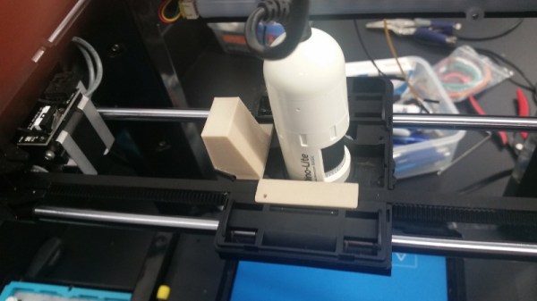
But thanks to the somewhat unusual nature of his printer, [Hammad Nasir] was able to take this concept a bit farther. Being considerably more rigid than the $99 acrylic-framed box of bolts we’ve become accustomed to, he was able to fit it with a basic spindle and use it for CNC engraving. He won’t be milling any steel on this rig, but judging by the pictures on the Hackaday.io page for the project, it does a respectable job cutting designs into plastic at least.

The IdeaWerk 3D printer that [Hammad] used for this project is phenomenally overbuilt. We don’t know whether the designers simply wanted to make it look futuristic and high-tech (admittedly, it does look like it could double as a movie prop) or they thought there was a chance it might get thrown down the stairs occasionally. In either event, it’s built like an absolute tank.

While the frame on lesser printers would likely flex as soon as the bit started moving across the workpiece, this thing isn’t going anywhere. Of course this machine is presumably still running on the standard GT2 belt and NEMA 17 arrangement that has been used in desktop 3D printers since the first wooden machines clattered to life. So while the frame might be ready to take some punishment, the drive system could respectfully disagree once the pressure is on.

Modification was simplified by the fact that the hotend and extruder assembly on the IdeaWerk is mounted to the X axis with just a single bolt. This makes it exceptionally easy to design alternate tool mounts, though arguably the 3D printed motor holder [Hammad] is using here is the weak link in the entire system; if it’s going to flex anywhere, it’s going to be there.

If you’re more photonically inclined, you might be interested in this similarly straightforward project that sees a 2.5 W laser module get bolted onto an entry level 3D printer.

HoloLens Brings Video Game Kart Racing To Life

There aren’t a lot of video game experiences we can easily recreate in the physical realm. You’ll quickly find that jumping on mushrooms in the real world doesn’t have nearly the same appeal as it does in Super Mario, and we won’t even get into the dangers of trying to recreate Frogger on your local multi-lane. But video game style go-kart racing? We have all the technology to pull that off, somebody just has to put all the pieces together.

Which is precisely what [Ian Charnas] is trying to do with his latest project. Using Microsoft’s HoloLens augmented reality headset, electric go-karts, 433 MHz wireless transceivers, and some Arduinos sprinkled in, he’s created the closest thing to Mario Kart that us flesh and blood mortals are likely to experience anytime soon.

The HoloLens headset worn by each driver overlays the necessary graphical elements like pickups and weapon effects, as well as puts over-the-top cartoon heads on the other racers. But of course, that’s only half of the story. Seeing the pickups and gadgets doesn’t do you any good if they don’t have any effect on the actual race.

To that end, [Ian] has come up with a way to control the performance of the go-karts using an electronic “backpack” that mounts to each kart. So speed boosting pickups actually make the kart go faster, and if a driver gets hit with a weapon fired at them, they get slowed down.

That’s the high-level version, anyway. There’s obviously a lot going on behind the scenes, some of which are detailed on the Hackaday.io page. One of the interesting notes is that the HoloLens needs visual markers to orient itself, which in the video after the break can be seen as black and white posters dotting the walls alongside the track. As the project progresses, [Ian] is hoping that these can be camouflaged in creative ways (such as being made to look like audience members or checkered flags) to make the overall experience more immersive.

According to [Ian], the next step is to find partners who want to help elevate this from a one-off project to something that you might actually see at an amusement park. We wish him luck, if for no other reason than we really want to play the thing ourselves. In the meantime, we’ll have to settle for racing hacked Power Wheels.

Continue reading “HoloLens Brings Video Game Kart Racing To Life”

Unlocking SIM Cards With A Logic Analyzer

[Jason Gin] wanted to reuse the SIM card that came with a ZTE WF721 wireless terminal he got from AT&T, but as he expected, it was locked to the device. Unfortunately, the terminal has no function to change the PIN and none of the defaults he tried seemed to work. The only thing left to do was crack it open and sniff the PIN with a logic analyzer.

This project is a fantastic example of the kind of reverse engineering you can pull off with even a cheap logic analyzer and a keen eye, but also perfectly illustrates the fact that having physical access to a device largely negates any security measures the manufacturer tries to implement. [Jason] already knew what the SIM unlock command would look like; he just needed to capture the exchange between the WF721 and SIM card, find the correct byte sequence, and look at the bytes directly after it.

Finding the test pads on the rear of the SIM slot, he wired his DSLogic Plus logic analyzer up to the VCC, CLK, RST, and I/O pins, then found a convenient place to attach his ground wire. After a bit of fiddling, he determined the SIM card was being run at 4 MHz, so he needed to configure a baud rate of 250 kbit/s to read the UART messages passing between the devices.

Once he found the bytes that signified successful unlocking, he was able to work his way backwards and determine the unlock command and its PIN code. It turns out the PIN was even being sent over the wire in plain text, though with the way security is often handled these days, we can’t say it surprises us. All [Jason] had to do then was put the SIM in his phone and punch in the sniffed PIN when prompted.

Could [Jason] have just run out to the store and picked up a prepaid SIM instead of cracking open this wireless terminal and sniffing its communications with a logic analyzer? Of course. But where’s the fun in that?