Analyzing Hobby Motors With An Oscilloscope

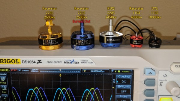
We always like finding new excuses reasons to use our test equipment, so we couldn’t help but be intrigued by this tip from [Joe Mosfet]. He uses the ever-popular Rigol DS1054Z to demonstrate the differences between a handful of brushless motors when rotated by his handheld drill at a constant RPM. Not only is he able to identify a blown motor, but it allows him to visualize their specifications which can otherwise seem a bit mystifying.

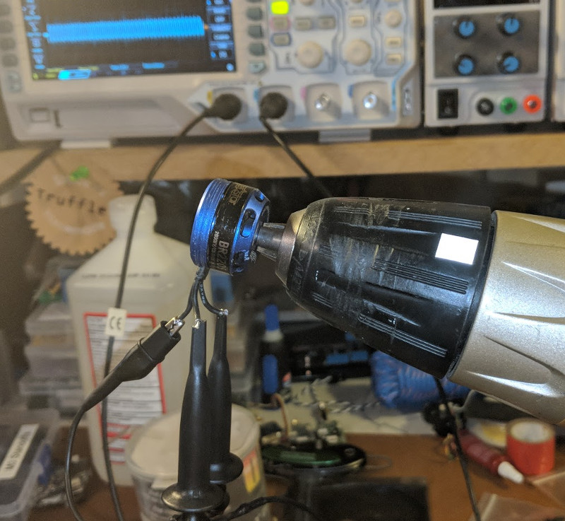
One wire from each motor is used as the ground, and channels one and two are connected to the remaining wires. Despite the DS1054Z having four channels, [Joe] is actually only using two of them here. The third channel being displayed is a virtual channel created by a math function on the scope.

After wiring them up, each motor got put into the chuck of his drill and spun up to 1430 RPM. The resulting waveforms were captured, and [Joe] walks us through each one explaining what we’re seeing on the scope.

The bad motor is easy to identify: the phases are out of alignment and in general the output looks erratic. Between the good motors, the higher the Kv rating of the motor, the lower voltage is seen on the scope. That’s because Kv in the context of brushless motors is a measurement of how fast the motor will spin for each volt. The inverse is also true, and [Joe] explains that if he could spin his 2450Kv motor at exactly 2450 RPM, we should see one volt output.

Beyond demonstrating the practical side of Kv ratings, [Joe] also theorizes that the shape of the wave might offer a glimpse into the quality of the motor’s construction. He notes his higher end motors generate a nice clean sine wave, while his cheaper ones show distortion at the peaks. An interesting note, though he does stress he can’t confirm there’s a real-world performance impact.

Last year we featured a similar method for identifying bad brushless motors using a drill press and an oscilloscope, but we liked that [Joe] went through the trouble of testing multiple motors and explaining the differences in their output.

[via /r/multicopter]

Building An Arduino Smart IC Tester For $25

There’s no question that you can get a lot done with the classic multimeter; it’s arguably the single most capable tool on your bench. But the farther down the rabbit hole of hacking and reverse engineering you go, the more extravagant your testing and diagnostic gear tends to get. For some of us that’s just an annoying reality of the game. For others it’s an excuse to buy, and maybe even build, some highly specialized equipment. We’ll give you one guess as to which group we fall into here at Hackaday.

[Akshay Baweja] is clearly a member of the second group. He’s recently published a guide on building a very slick intelligent Integrated Circuit tester with a total cost of under $25 USD. Whether you’re trying to identify an unknown chip or verifying your latest parts off the slow-boat from China actually work before installing them in your finished product, this $25 tool could end up saving you a lot of time and aggravation.

[Akshay] walks readers through the components and assembly of his IC tester, which takes the form of a Shield for the Arduino Mega 2560. The custom PCB he designed and had manufactured holds the 20 Pin ZIF Socket as well as the 2.4 inch TFT touch screen. The screen features an integrated micro SD slot which is important as you need the SD card to hold the chip database.

With an IC to test inserted into the ZIF socket, the user can have the tester attempt to automatically ID the chip or can manually enter in a part number to lookup. The source code for the Arduino as well as the chip ID database is up on GitHub for anyone looking to add some more hardware to the device’s testing repertoire.

The importance of good test equipment simply cannot be overstated. Between highly specialized gear like this IC tester to classic instruments such as the oscilloscope, your bench is going to be full of weird and wonderful pieces of equipment before too long.

Continue reading “Building An Arduino Smart IC Tester For $25”

Printed Motorcycle Choke Lever Goes The Distance

We all dread the day that our favorite piece of hardware becomes so old that spare parts are no longer available for it, something about facing that mechanical mortality sends a little shiver up the hacker’s spine. But on the other hand, the day you can’t get replacement hardware is also the same day you have a valid excuse to make your own parts.

3D rendering above the 2D scan

That’s the situation [Jonathan] found himself in when the choke lever for his Suzuki motorcycle broke. New parts aren’t made for his bike anymore, which gave him the opportunity to fire up Fusion 360 and see if he couldn’t design a replacement using a 2D scan of what was left of the original part.

[Jonathan] put the original part on his flatbed scanner as well one of his credit cards to use for a reference point to scale the image when he imported it into Fusion 360. Using a 2D scanner to get a jump-start on your 3D model is a neat trick when working on replacement parts, and one we don’t see as much as you might think. A proper 3D scanner is cool and all, but certainly not required when replicating hardware like this.

The choke lever is a rather complex shape, one of those geometries that doesn’t really have a good printing orientation because there are overhangs all over the place. That combined with the fact that [Jonathan] printed at .3mm layer height for speed gives the final part an admittedly rough look, but it works. The part was supposed to be a prototype before he reprinted it at higher resolution and potentially with a stronger material like PETG, but after two years the prototype is still installed and working fine. This isn’t the first time we’ve seen a “temporary” 3D printed part become a long-term solution.


This is an entry in Hackaday’s

Repairs You Can Print contest

The twenty best projects will receive $100 in Tindie credit, and for the best projects by a Student or Organization, we’ve got two brand-new Prusa i3 MK3 printers. With a printer like that, you’ll be breaking stuff around the house just to have an excuse to make replacement parts.


Create A Discord Webhook With Python For Your Bot

Discord is an IRC-like chat platform that all the young cool kids are hanging out on. Originally intended as a way to communicate during online games, Discord has grown to the point that there are servers out there for nearly any topic imaginable. One of the reasons for this phenomenal growth is how easy it is to create and moderate your own Discord server: just hit the “+” icon on the website or in the mobile application, and away you go.

As a long-time IRC guy, I was initially unimpressed with Discord. It seemed like the same kind of stuff we’ve had for decades, but with an admittedly slick UI. After having used it for a few months now and joining servers dedicated to everything from gaming to rocket science, I can’t say that my initial impression of Discord is inaccurate: it’s definitely just a modern IRC. But I’ve also come to the realization that I’m OK with that.

But this isn’t a review of Discord or an invitation to join the server I’ve setup for my Battlefield platoon. In this article we’re going to look at how easy it is to create a simple “bot” that you can plug into a Discord server and do useful work with. Since anyone can create a persistent Discord server for free, it’s an interesting platform to use for IoT monitoring and logging by simply sending messages into the server.

Continue reading “Create A Discord Webhook With Python For Your Bot”

Arduino Keyboard Is Gorgeous Inside And Out

While the vast majority of us are content to plod along with the squishy chiclet keyboards on our laptops, or the cheapest USB membrane keyboard we could find on Amazon, there’s a special breed out there who demand something more. To them, nothing beats a good old-fashioned mechanical keyboard, where each key-press sounds like a footfall of Zeus himself. They are truly the “Chad” of the input device world.

But what if even the most high end of mechanical keyboards doesn’t quench your thirst for spring-loaded perfection? In that case, the only thing left to do is design and build your own. [Matthew Cordier] recently unveiled the custom mechanical keyboard he’s been working on, and to say it’s an elegant piece of engineering is something of an understatement. It may even look better inside than it does on the outside.

The keyboard, which he is calling z.48, is based around the Arduino Pro Micro running a firmware generated on kbfirmware.com, and features some absolutely fantastic hand-wiring. No PCBs here, just a rainbow assortment of wire and the patience of a Buddhist monk. The particularly attentive reader may notice that [Matthew] used his soldering iron to melt away the insulation on his wires where they meet up with the keys, giving the final wiring job a very clean look.

Speaking of the keys, they are Gateron switches with DSA Hana caps. If none of those words mean anything to you, don’t worry. We’re through the Looking Glass and into the world of the keyboard aficionado now.

Finally, the case itself is printed on a CR-10 with a 0.3 mm nozzle and 0.2 mm layers giving it a very fine finish. At 70% infill, we imagine it’s got a good deal of heft as well. [Matthew] mentions that a production case and a PCB are in the cards for the future as he hopes to do a small commercial run of these boards. In the meantime we can all bask in the glory of what passes for a prototype in his world.

We’ve seen some exceptionally impressive mechanical keyboards over the years, including the occasional oddity like the fully 3D printed one and even one that inexplicably moves around. But this build by [Matthew] has to be one of the most elegant we’ve ever come across.

AT-ST High Chair Elevates Lucky Jedi Youngling

As a new parent, there’s lots you have to do. You have to buy a car seat, get the baby’s room ready, figure out daycare; all the boring but unavoidable minutiae of shepherding a tiny human. But for the more creative types, that list might include warming up the 3D printer or putting a fresh bit in the CNC, as there’s no better way to welcome a little one into the world than giving them some custom gear to get started with.

That’s certainly been the plan for [Matthew Regonini], who’s been showering his son with DIY playthings. He recently wrote in to tell us about his awesome AT-ST high chair build that manages to turn the drudgery of getting a baby to eat into an epic worthy of a John Williams score.

This isn’t the first time [Matthew] has turned dead trees into Imperial hardware. Last year we covered his fantastic AT-AT rocker which utilized the same construction techniques. The parts are cut out of plywood with his CNC, separated, cleaned up on a spindle sander, and finally assembled with wood glue and a few strategic fasteners. The depth and level of detail he’s able to achieve when the individual pieces are stacked up is exceptionally impressive. If builds like these don’t get you thinking about adding a CNC to your workshop, nothing will.

As with the AT-AT, the finish on the high chair is simply a healthy application of polyurethane. This keeps the wood from being porous (important as this build will be seeing its fair share of food and liquids) while retaining a natural look. Some might be tempted to paint it up in appropriate Imperial colors, but that might be a bit imposing considering its intended occupant.

Really, the only downside with this build is how quickly his son will outgrow it. The obvious solution to the problem is a constant supply of fresh babies to pilot it, but that’s one type of creation that we don’t generally detail here on Hackaday. If you have questions, ask your parents.

Incidentally, it’s starting to look like we’ve got a plywood arms-race going on. We’re excited to see somebody take it to the next level. A little scared, but mainly excited.

Continue reading “AT-ST High Chair Elevates Lucky Jedi Youngling”

Tearing Down A $1000 E-Ink Display

Back in 2016, Chinese company Dasung blew past their Indiegogo goal to fund the Paperlike: the world’s first general purpose E-Ink display. Rather than being stuck in a reader from your favorite purveyor of DRM like previous displays, the Paperlike could be used with whatever device you wanted; albeit in black and white and at a relatively low refresh rate. It promised to allow reading and writing on your computer or tablet without needing a backlight. The price was steep at $800 USD for a 13″ display, but clearly enough people were interested to make the device a reality.

At least they have a sense of humor about it.

You can count [Kev Zettler] among the Paperlike devotees. He’s such a fan of the technology that he’s on the road to building a DIY E-Ink laptop using the latest generation Paperlike Pro. But before he can do that, he’s got to take the thing apart and see how it ticks. While a lot of the proprietary magic that makes the display work is still a mystery, he does his best to document the internals for those of us who are a bit to shy to take a screwdriver to a display that costs $1,000.

It looks like the Paperlike Pro is designed (either intentionally or otherwise) to look a bit like the Amazon Kindle, and the construction method is unfortunately the same. The front panel is glued on, and needs to be peeled off by getting under it with something sharp and prying it off carefully. For a $100 e-reader we can deal with that, but for as much as the Paperlike Pro costs that kind of disassembly gives us the chills.

He’s identified the bare display module as a 13.3 inch ED133UT2, which led him down an interesting path investigating other displays in the same family. It turns out the one Dasung went with is essentially the low end of the spectrum. The display has glare issues and is permanently bonded to a piece of glass, whereas other models in the same family boast not only flexibility but anti-glare coatings. There’s even one with integrated touch screen. [Kev] mentions that one of those displays would be much better for his E-Ink laptop project, but we’re assuming he’s not going to toss this thing in the bin just because there’s better options out there.

Beyond the display itself there’s a custom Dasung control board that [Kev] says is a bit too complex for him to decipher, made especially difficult thanks to the fact that the chips have had their labels removed. One interesting discovery though was the USB port which is officially supposed to be just for power has all four wires connected to the main board, raising the possibility of some future software hacking.

You might not know this, but hackers absolutely love E-Ink. We’ve covered some very impressive projects utilizing this paper-like tech in the past, from an entry in our 2017 Hackaday Prize to the chemistry involved in homebrewing your own displays.