WiFiWart Linux Pentesting Device Gets First PCBs

When we last checked in on the WiFiWart, an ambitious project to scratch-build a Linux powered penetration testing drop box small enough to be disguised as a standard phone charger, it was still in the early planning phases. In fact, the whole thing was little more than an idea. But we had a hunch that [Walker] was tenacious enough see the project through to reality, and now less than two months later, we’re happy to report that not only have the first prototype PCBs been assembled, but a community of like minded individuals is being built up around this exciting open source project.
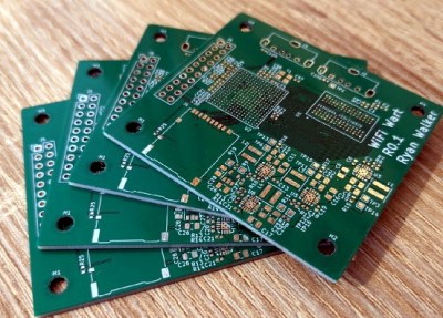
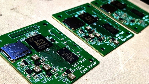
Now before you get too excited, we should probably say that the prototypes didn’t actually work. Even worse, the precious Magic Smoke was released from the board’s Allwinner A33 ARM SoC when a pin only rated for 2.75 V was inadvertently fed 3.3 V. The culprit? Somehow [Walker] says he mistakenly ordered a 3.3 V regulator even though he had the appropriate 2.5 V model down in the Bill of Materials. A bummer to be sure, but that’s what prototypes are for.

Even though [Walker] wasn’t able to fire the board up, the fact that they even got produced shows just how much progress has been made in a relatively short amount of time. A lot of thought went into how the 1 GB DDR3 RAM would get connected to the A33, which includes a brief overview of how you do automatic trace length matching in KiCad. He’s also locked in component selections, such as the RTL8188CUS WiFi module, that were still being contemplated as of our last update.
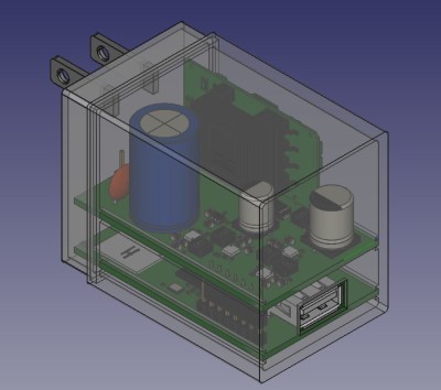
Multiple boards make better use of vertical space.

Towards the end of the post, he even discusses the ultimate layout of the board, as the one he’s currently working on is just a functional prototype and would never actually fit inside of a phone charger. It sounds like the plan is to make use of the vertical real estate within the plastic enclosure of the charger, rather than trying to cram everything into a two dimensional design.

Want to get in on the fun, or just stay updated as [Walker] embarks on this epic journey? Perhaps you’d be interested in joining the recently formed Open Source Security Hardware Discord server he’s spun up. Whether you’ve got input on the design, or just want to hang out and watch the WiFiWart get developed, we’re sure he’d be happy to have you stop by.

The first post about this project got quite a response from Hackaday readers, and for good reason. While many in the hacking and making scene only have a passing interest in the security side of things, we all love our little little Linux boards. Especially ones that are being developed in the open.

Your PC Sound Card As A Sensor Input

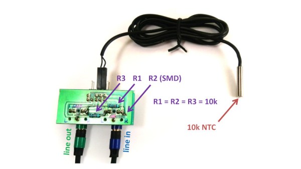
The commoditised PC is the most versatile tool many of us will own, and since it has been around for a very long time it is also something that can be found for free or very cheaply if the latest components aren’t a concern. It’s not without limitations though, while it’s designed for expansion it no longer has any ports that can easily be repurposed as GPIOs for reading sensors. A solution for some sensors comes courtesy of [Ruslan Nagimov], who shows us how the PC sound card can become a measurement interface.

The idea is that simple resistive or capacitive sensors can be read through their AC characteristics by sending out a sine wave on one channel of the card and reading the result on the other from a divider circuit. He goes extensively into the code, both for the resistive example and for reactive components, and we can see that it forms a handy extension to the PC capabilities.

We’re sure this technique will find applications for some readers, but it interests us for another platform. Measurement using a mobile phone’s audio jack doesn’t have an inspiring history, but perhaps this could be used as well for mobile sensors.

The Devil Is In The Details

If you’ve taken a physics class, you’ve doubtless heard tales of mythical beasts like the massless string, the frictionless bearing, and the perfect sphere. And if you’re designing something new, it’s not always wrong to start by thinking in terms of these abstractions, just to get the basic framework laid and a first-order handle on the way things go. But once you start building, you’d better be ready to shed your illusions that a 6 mm peg will fit into a 6 mm hole.

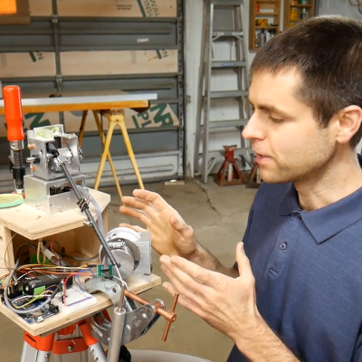
Theory and practice are the same thing, in theory. But as soon as you step into practice, your “weekend build” can easily turn into a 500-hour project, full of hurdles, discoveries, experimentation, and eventual success. I’m not going to rehash [Scott Rumschlag]’s project here — you should really watch his detailed video — but suffice it to say that when building a sub-millimeter precision 3D measuring device, bearings do have friction and string does have non-zero mass, and it all matters.

When you start working on a project that “looked good on paper” or for whatever reason just doesn’t turn out as precisely as you’d wished, you could do worse than to follow [Scott’s] example: start off by quantifying your goals, and then identify where every error along the way accumulates to keep you from reaching them. Doing precise work isn’t easy, but it’s not impossible either if you know where all the errors are coming from. You at least have a chain of improvements that you can consider, and if you’ve set realistic goals, you also know when to stop, which is almost as important.

And if anyone out there has an infinite sheet of perfectly conductive material, I’m in the market.

A Custom Raspberry Pi Spotted In The Wild

Since the first Raspberry Pi came to market back in 2012 there have been a variety of models released. Some of them are rarer than others, and unusual boards can even be rather sought-after. This one spotted at a Thai junk vendor won’t be in the hands of many collectors though, and investigating it sheds a bit of light on some of the most unusual boards from the company.

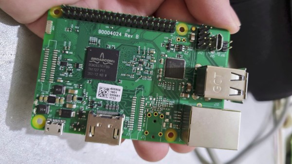
The board is recognisably very similar to a Pi 3 with a BCM2837 SoC, but despite all that it has no Pi logo. On the underside there is an eMMC in place of the SD socket, and one pair of USB sockets has been replaced by a micro USB socket and a header. The source is reported to have been a washing machine, but given that this SoC is exclusive to the the Pi Foundation there’s no way it could easily have been manufactured by anyone else. The answer comes in the 2015 launch of a customisation service for industrial customers, which allowed manufacturers to have their own versions made of the fruity SBC.

From the point of view of an experimenter this board offers nothing that a standard device can’t do. But it’s an interesting glimpse of an unseen side to the Pi story, and it holds the prospect of other special versions being unearthed. If you find one on your travels, let us know!

3D Zoetrope Uses Illusion To Double The Frames

Although film and animation have come quite a long way, there’s still something magical about that grandaddy of them all, the zoetrope. Thanks to persistence of vision, our eyes are fooled into seeing movement where there is none, only carefully laid-out still pictures strobing under the right lighting.

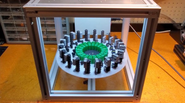
After four months of research, CAD, prototyping, and programming, [Harrison McIntyre] has built a 3D zoetrope that brings a gif to glorious physical life (video, embedded below). All the image pieces are printed and move under a fancy backlight that [Harrison] borrowed from work. It works essentially the same as a 2D zoetrope, as long as you get the spacing juuuuust right. 360° divided by 20 frames comes out to 18° per frame. So a motor spins the disk around, and every 18°, the light pulses for one millisecond and then turns off until the next frame is in position.

The really interesting thing is that there are actually more than 20 frames at play here. If you follow a single character through the loop, it takes 46 frames to complete the animation thanks to something 3D zoetrope pioneer [Kevin Holmes] dubbed ‘animation multiplexing‘, which in [Harrison]’s example, is easily explained as a relay race in which all runners run their section at the same time, creating the illusion of constant motion.

There’s more than one way to use a 3D printer to create a zoetrope, and we doubt we would have ever thought of this one that squashes four dimensions into three.

Continue reading “3D Zoetrope Uses Illusion To Double The Frames”

Understanding Custom Signal Protocols With Old Nintendos

For retro gaming, there’s really no substitute for original hardware. As it ages, though, a lot of us need to find something passable since antique hardware won’t last forever. If a console isn’t working properly an emulator can get us some of the way there, but using an original controller is still preferred even when using emulators. To that end, [All Parts Combined] shows us how to build custom interfaces between original Nintendo controllers and a PC.

The build starts by mapping out the controller behavior. Buttons on a SNES controller don’t correspond directly to pins, rather a clock latches all of the button presses at a particular moment all at once during each timing event and sends that information to the console. To implement this protocol an Adafruit Trinket is used, and a thorough explanation of the code is given in the video linked below. From there it was a simple matter of building the device itself, for which [All Parts Combined] scavenged controller ports from broken Super Nintendos and housed everything into a tidy box where it can be attached via USB to his PC.

While it might seem like a lot of work to get a custom Nintendo controller interface running just because he had lost his Mega Man cartridge, this build goes a long way to understanding a custom controller protocol. Plus, there’s a lot more utility here than just playing Mega Man; a method like this could easily be used to interface other controllers as well. We’ve even seen the reverse process where USB devices were made to work on a Nintendo 64.

Continue reading “Understanding Custom Signal Protocols With Old Nintendos”

$10 000 Physics Wager Settles The Debate On Sailing Downwind Faster Than The Wind

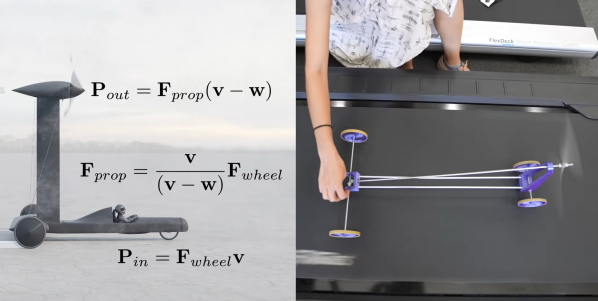
By now, many of you have seen the video of [Rick Cavallaro]’s Blackbird, the controversial wind-powered land vehicle that can outrun the wind. The video has led to a high-profile $10 000 wager between [Derek Muller] aka [Veritasium] and [Alex Kusenko], a professor of physics from UCLA. [Veritasium] won the wager with the help of a scale model built by [Xyla Foxlin], and you need to watch the videos after the break for some excellent lessons in physics, engineering, and civilized debate.

After seeing [Veritasium]’s video on Blackbird, [Professor Kusenko] contacted him and said the performance claims and explanation were incorrect. After a bit of debate [Veritasium] proposed a wager on the matter, which [Professor Kusenko] accepted, and it was made official with a written agreement witnessed by [Neil deGrasse Tyson], [Bill Nye], and [Sean Carrol]. From the start, it was agreed that the entire debate would be made public.

[Professor Kusenko] made a very thorough and convincing argument, backed by calculations, against the claims in the video. He claimed the observations were due to a combination of gusty winds, a vertical wind gradient. He was convinced and that the vehicle would not be able to maintain a speed higher than the wind, directly downwind. By [Veritasium]’s own admittance, his original video could have contained more details and proof of performance claims of the Blackbird vehicle. He added these to the latest video and included two model demonstrations. The model that brought the concept home for us is at 13:46 in the video, and substitutes the propeller for a large wheel being driven by a piece of lumber being bushed across it. The second model, built by [Xyla Foxlin] was designed to demonstrate the concept on a treadmill. The 4th version of [Xyla]’s model was the first to be successful after she found out from [Rick Cavallaro] that the key design detail is the Vehicle Speed Ratio, which must be 0.7 or less. It is the pitch of the propeller divided by the circumference of the driven wheel, assuming a 1:1 gear ratio. All the 3D files and details are available if you want to build your own downwind cart. Continue reading “$10 000 Physics Wager Settles The Debate On Sailing Downwind Faster Than The Wind”