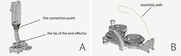
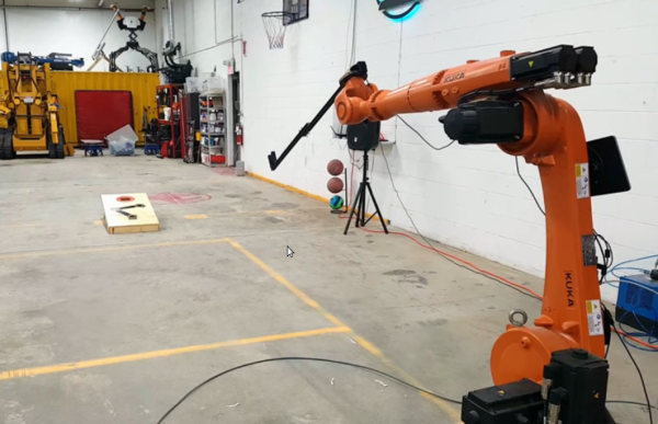
Legged Robots Put On Wheels And Skate Away

We don’t know how much time passed between the invention of the wheel and someone putting wheels on their feet, but we expect that was a great moment of discovery: combining the ability to roll off at speed and our leg’s ability to quickly adapt to changing terrain. Now that we have a wide assortment of recreational wheeled footwear, what’s next? How about teaching robots to skate, too? An IEEE Spectrum interview with [Marko Bjelonic] of ETH Zürich describes progress by one of many research teams working on the problem.

For many of us, the first robot we saw rolling on powered wheels at the end of actively articulated legs was when footage of the Boston Dynamics ‘Handle’ project surfaced a few years ago. Rolling up and down a wide variety of terrain and performing an occasional jump, its athleticism caused quite a stir in robotics circles. But when Handle was introduced as a commercial product, its job was… stacking boxes in a warehouse? That was disappointing. Warehouse floors are quite flat, leaving Handle’s agility under-utilized.

Boston Dynamic has typically been pretty tight-lipped on details of their robotics development, so we may never know the full story behind Handle. But what they have definitely accomplished is getting a lot more people thinking about the control problems involved. Even for humans, we face a nontrivial learning curve paved with bruised and occasionally broken body parts, and that’s even before we start applying power to the wheels. So there are plenty of problems to solve, generating a steady stream of research papers describing how robots might master this mode of locomotion.

Adding to the excitement is the fact this is becoming an area where reality is catching up to fiction, as wheeled-legged robots have been imagined in forms like Tachikoma of Ghost in the Shell. While those fictional robots have inspired projects ranging from LEGO creations to 28-servo beasts, their wheel and leg motions have not been autonomously coordinated as they are in this generation of research robots.

As control algorithms mature in robot research labs around the world, we’re confident we’ll see wheeled-legged robots finding applications in other fields. This concept is far too cool to be left stacking boxes in a warehouse.

Continue reading “Legged Robots Put On Wheels And Skate Away”

Casting Skateboard Wheels With A 3D Printed Mold

We’ll admit that most of the Hackaday staff wouldn’t get too far on a skateboard, but that doesn’t mean we can’t appreciate the impressive DIY wheels that [Chris McCann] has managed to cast using 3D printed molds. From unique color combinations to experimental materials, the process certainly opens up some interesting possibilities for those looking to truly customize their rides. Though it’s worth noting there’s a certain element of risk involved; should a set of homemade wheels fail at speed, it could go rather poorly for the rider.

Both the STL and STEP files for the mold have been released under the Creative Commons Attribution 4.0 license, meaning anyone with a 3D printer can follow along at home. Unfortunately, it’s not quite as simple as clicking print and coming back to a usable mold. Because of the layer lines inherent to FDM 3D printing, the inside of the mold needs to be thoroughly sanded and polished. [Chris] mentions that printing the mold in ABS and using vapor smoothing might be a workable alternative to elbow grease and PLA, but he hasn’t personally tried it yet.

Once you’ve got the three part mold printed, smoothed, and coated with an appropriate release agent like petroleum jelly, it’s time to make some wheels. The core of each wheel is actually 3D printed from PETG, which should give it pretty reasonable impact resistance. If you have access to a lathe, producing aluminum cores shouldn’t be too difficult either. With the core loaded into the mold, urethane resin is poured in through the top until all the empty space is filled.

But you’re not done yet. All those little air bubbles in the resin need to be dealt with before it cures. [Chris] puts his filled molds into a pressure chamber, though he mentions that vacuum degassing might also be a possibility depending on the urethane mixture used. After everything is solidified, the mold can easily be taken apart to reveal the newly cast wheel.

While there’s often some trial and error involved, 3D printing and resin casting are an undeniably powerful combination. If you can master the techniques involved, you can produce some very impressive parts that otherwise would be exceptionally difficult to produce on a hacker’s budget. Especially when you’re ready to start casting molten metal.

Continue reading “Casting Skateboard Wheels With A 3D Printed Mold”

No Doorknobs Needed For This Nitrogen Laser Build

Sometimes the decision to tackle a project or not can boil down to sourcing parts. Not everything is as close as a Digi-Key or Mouser order, and relying on the availability of surplus parts from eBay or other such markets can be difficult. Knowing if and when a substitute will work for an exotic part can sometimes be a project all on its own.

Building lasers is a great example of this, and [Les Wright] recently looked at substitutes for hard-to-find “doorknob” capacitors for his transversely excited atmospheric lasers. We took at his homebrew TEA lasers recently, which rely on a high voltage supply and very rapid switching to get nitrogen gas to lase. His design uses surplus doorknob caps, big chunky parts rated for very high voltages but also with very low parasitic inductance, which makes them perfect for the triggering circuit.

[Les] tried to substitute cheaper and easier-to-find ceramic power caps with radial wire leads rather than threaded lugs. With a nominal 40-kV rating, one would expect these chunky blue caps to tolerate the 17-kV power supply, but as he suspected, the distance between the leads was short enough to result in flashover arcing. Turning down the pressure in the spark gap chamber helped reduce the flashover and prove that these caps won’t spoil the carefully engineered inductive properties of the trigger. Check out the video below for more details.

Thanks to [Les] for following up on this and making sure everyone can replicate his designs. That’s one of the things we love about this community — true hackers always try to find a way around problems, even when it’s just finding alternates for unobtanium parts.

Continue reading “No Doorknobs Needed For This Nitrogen Laser Build”

Webcam Heart Rate Monitor Brings Photoplethysmography To Your PC

It seems like within the last ten years, every other gadget to be released has some sort of heart rate monitoring capability. Most modern smartwatches can report your BPMs, and we’ve even seen some headphones with the same ability hitting the market. Most of these devices use an optical measurement method in which skin is illuminated (usually by an LED) and a sensor records changes in skin color and light absorption. This method is called Photoplethysmography (PPG), and has even been implemented (in a simple form) in smartphone apps in which the data is generated by video of your finger covering the phone camera.

The basic theory of operation here has its roots in an experiment you probably undertook as a child. Did you ever hold a flashlight up to your hand to see the light, filtered red by your blood, shine through? That’s exactly what’s happening here. One key detail that is hard to perceive when a flashlight is illuminating your entire hand, however, is that deoxygenated blood is darker in color than oxygenated blood. By observing the frequency of the light-dark color change, we can back out the heart rate.

This is exactly how [Andy Kong] approached two methods of measuring heart rate from a webcam.

Method 1: The Cover-Up

The first detection scheme [Andy] tried is what he refers to as the “phone flashlight trick”. Essentially, you cover the webcam lens entirely with your finger. Ambient light shines through your skin and produces a video stream that looks like a dark red rectangle. Though it may be imperceptible to us, the color changes ever-so-slightly as your heart beats. An FFT of the raw data gives us a heart rate that’s surprisingly accurate. [Andy] even has a live demo up that you can try for yourself (just remember to clean the smudges off your webcam afterwards).

Method 2: Remote Sensing

Now things are getting a bit more advanced. What if you don’t want to clean your webcam after each time you measure your heart rate? Well thankfully there’s a remote sensing option as well.

For this method, [Andy] is actually using OpenCV to measure the cyclical swelling and shrinking of blood vessels in your skin by measuring the color change in your face. It’s absolutely mind-blowing that this works, considering the resolution of a standard webcam. He found the most success by focusing on fleshy patches of skin right below the eyes, though he says others recommend taking a look at the forehead.

Every now and then we see something that works even though it really seems like it shouldn’t. How is a webcam sensitive enough to measure these minute changes in facial color? Why isn’t the signal uselessly noisy? This project is in good company with other neat heart rate measurement tricks we’ve seen. It’s amazing that this works at all, and even more incredible that it works so well.

Better Security, Harry Potter Style

We all know we shouldn’t use 1234 as our password. But we often don’t do the absolute best practice when it comes to passwords. After all, you should have some obscure strange password that is unique for every site. But we all have lots of passwords, so most of us use $pock2020 or something like that. If you know I’m a Star Trek fan, that wouldn’t be super hard to guess. [Phani] writes about a technique called Horcruxing — a term taken from the literary realm of Harry Potter that allowed Voldemort to preserve life by splitting it into multiple parts, all of which were required to bring an end to his villany. [Phani’s] process promises to offer better security than using a single password, without the problems associated with having hundreds of random passwords.

Most people these days use some form of password manager. That’s great because the manager can create 48 character passwords of random words or symbols and even you don’t know the password. Of course, you do know the master password or, at least, you better. So if anyone ever compromised that password, they’d have all your passwords at their fingers. Horcruxing makes sure that the password manager doesn’t know the entire password, just the hard parts of it.

Continue reading “Better Security, Harry Potter Style”

Making Smart Bulbs Smarter With The Power Of MQTT

What’s the point of smart home automation? To make every day tasks easier, of course! According to [Tomasz Cybulski], that wasn’t the case when he installed IKEA smart lights in his closet. It’s handy to have them in a common switch, in this case a remote control, but having to look for it every time he needed the lights could use some improvement. Enter his project to make smart bulbs smarter, through the use of a simple ESP8266.

While hooking a door switch to the lights’ power supply could provide a quick solution, [Tomasz]’s wife wanted to keep the functionality of the remote control, so he had to look elsewhere. These light bulbs use the simple Zigbee protocol, so arranging for other devices was rather trivial. A USB dongle to interface with the protocol was configured for his existing Raspberry Pi automation controller, while an ESP8266 served as the real-world sensor by connecting it to reed switches installed in the closet doors.

With all the hardware sorted out, it’s a simple matter of making it all talk to each other. The ESP8266, using the Tasmota firmware, sends a signal to an MQTT server running on the Raspberry Pi, which in turn translates it to a remote trigger on the Zigbee frequency with the dongle. The lights turn on when the door opens, and off again once it closes. And since there were no further modifications to the lights themselves, the original IKEA controller still works as expected, which we’re sure [Tomasz]’s wife appreciates!

MQTT can be an interesting piece of software that goes beyond just home automation though, and if you already have a server in your home you can use it to transfer your clipboard’s contents to another device. If you are using it for home automation though, here’s an inspiration for a rather unusual dashboard to keep things interesting. Check out this hack in action after the break.

Continue reading “Making Smart Bulbs Smarter With The Power Of MQTT”

Modified Yost Tames Pinout Plethora

Every hacker has an assortment of USB to TTL-serial adapters kicking around in their lab, and we have all been annoyed that each one has a different pinout. You layout a PCB or breadboard for the Sparkfun flavor (GND, CTS, VCC, TXD, RXD, DTR), but when you begin troubleshooting all you can find is a CH340 board (GND, +5V, TXD, RXD, DTR, +3.3V). You have to jumper everything, and it becomes a mess. It wasn’t much better back in the days of RS-232 level signaling, either. While the pinouts were consistent, there were other headaches. Did the connection need a NULL modem adaptor? And if you were unlucky, you might need a DB-25 to DE-9 adaptor, and the really unlucky might need one or more gender changers. Surely there’s a better way.

It turns out there was a better way, although it didn’t seem to have become as popular as one might expect. Back in 1987 [Dave Yost] formalized an interconnection scheme using RJ45 plugs and jacks while at Berkeley.  The signals were arranged in a mirrored fashion so that each cable is always a crossover — just plug two cables back-to-back if you really need a straight thru connection.

Even though he was dealing with RS-232 serial, nothing prevents us from using this scheme for logic level signaling. For example, consider the following 1×10 header pinout, where the original 8-pins are expanded to 10 to allow for power:

This is an extreme example, and can obviously be shrunk depending on how much handshaking, if any, or power is desired. Such a pinout lets you switch between DCE and DTE by simply flipping the connector around. And if a Dupont-style header slips off too easily in your applications, you could always use an RJ connector. This still doesn’t solve the Tower of Babel pinout problem with the USB-TTL adaptors. But standardizing on a serial pinout such as this for your projects and making cables or kludging your TTL adaptors will make serial debugging less painful.

Yost to Sparkfun Adaptor Cable

Back when he released this scheme in 1987, [Dave] pontificated:

“Maybe one day before the year 2,000, the world will have a new, simple, high-speed, flow-controlled, standard type of connection for point-to-point applications currently using RS-232, with an adaptor available to talk to old, RS-232 equipment.”

Let us know your thoughts in the comments below.