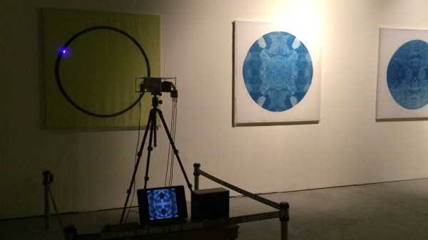
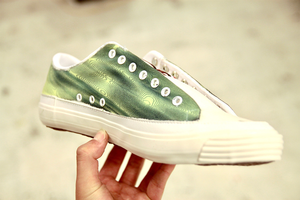
How do you get an inkjet head on a shoe or a couch? Most printing processes require a flat surface to print. But hearkening back to the days when a blueprint was a blueprint, a mixture of an iron salt and an acid are mixed and applied to a surface an interesting reaction occurs when the surface is exposed to UV light. The chemicals react to form, of all things, prussian blue. After the reaction occurs simply washing away the remaining chemicals leaves a stable print behind.
[Shih Wei Chieh] uses two galvanometers and a laser to cure the fabric. He uses a slightly newer process which reduces the exposure time required. This lets him print very large pictures, but also on uneven surfaces. As you can see in the video, viewable after the break, the effect is very pretty. There’s a new way to have the coolest pen plotter on the block.
You might think it is strange that a story about technology would start off talking about Wonder Woman. When you realize the technology in question is a lie detector, you might think, “Oh, that’s right. Wonder Woman had the lasso of truth, so this is just a lame association.” You might think that, but you’d be wrong. Turns out, Wonder Woman and real life polygraphs have a much deeper connection; both the polygraph and Wonder Woman share a common creator.
It makes a good story to say that William Marston — an internationally famous psychologist — created the polygraph, but as you might expect it wasn’t the result of a single person’s effort. However, Marston played a key role and also was behind promoting the technology. So, too, even though he is credited as Wonder Woman’s sole creator, the truth is probably a bit more complex.
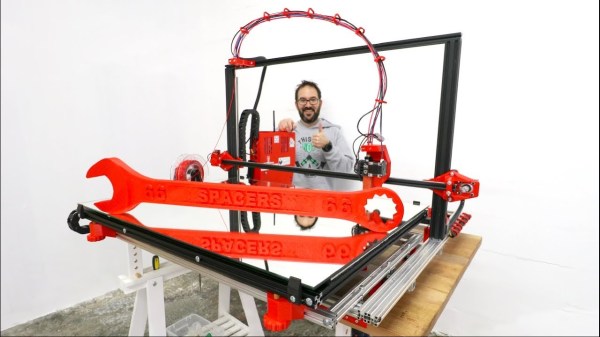
Established FDM 3D printers designs generally lead themselves well to being scaled up, as long as you keep frame stiffness, alignment and movement in mind. [Ivan Miranda] needed a big printer for his big projects (videos below), so he built his own i3 style printer with a 800 mm × 500 mm usable print bed and about 500 mm vertical print height.
The frame of the new machine is built using 20×20 and 20×40 aluminium V-slot extrusions with some square tubing for reinforcement. To move all the weight, all 3 axes are driven by double NEMA17 steppers, via a DUET3D board with an expansion board for the extra motors. The extruder is the new E3D Hemera with a 0.8 mm nozzle. The print bed is a mirror, on top of the aluminium plate, headed by a large silicone heat pad. The first bed version used a smaller heat pad directly on the back of the mirror, but it heated up unevenly and the mirror ended up cracking. Look out for the ingeniously lightweight and simple cable management to the extruder. When all was said and done he printed a 800 mm long size 66 wrench as a test piece with zero warp, which is pretty good even for PLA. This project is also a perfect example of the power of 3D printing for rapid iterative development, as lot of the printed fittings went through multiple versions.
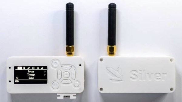
[Foaly] has been hard at work making an open-source long range camera remote, and recently shared a deeply thoughtful post about how it is never too early to consider all aspects of design, lest it cost you in the end. It all started with designing an enclosure for a working prototype, and it led to redesigning the PCB from scratch. That took a lot of guts, and we recommend you make some time to click that link and read up on what he shared. You’ll either learn some valuable tips, or just enjoy nodding sagely as he confirms things you already know. It’s win-win.
Note the awkward buttons right next to the antenna connector, for example.
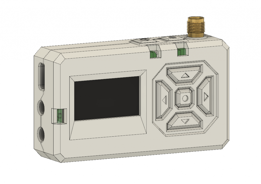
The project in question is Silver, and calling it a camera remote is selling it a bit short. In any case, [Foaly] had a perfectly serviceable set of prototypes and needed a small batch of enclosures. So far so normal, but in the process of designing possible solutions, [Foaly] ran into a sure-fire sign that a project is in trouble: problems cropping up everywhere, and in general everything just seeming harder than it should be. Holding the mounting-hole-free PCB securely never seemed quite right. Buttons were awkward to reach, ill-proportioned, and didn’t feel good to use. The OLED screen’s component was physically centered, but the display was off-center which looked wrong no matter how the lines of the bezel were sculpted. The PCB was a tidy rectangle, but the display ended up a bit small and enclosures always looked bulky by the time everything was accounted for. The best effort is shown here, and it just didn’t satisfy.
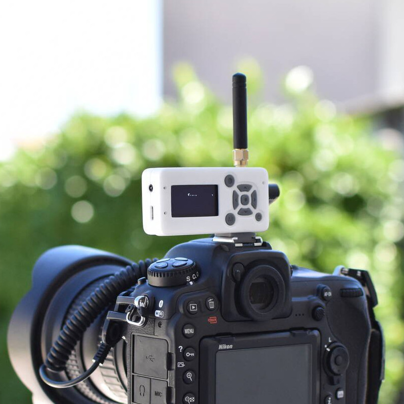
[Foaly] says the real problem was that he designed the electronics and did the layout while giving some thought (but not much thought) to their eventual integration into a case. This isn’t necessarily a problem for a one-off, but from a product design perspective it led to so many problems that it was better to start over, this time being mindful of how everything integrates right from the start: the layout, the components, the mechanical bits, the assembly, and the ultimate user experience. The end result is wonderful, and we’re delighted [Foaly] took the time to document his findings.
We imagine most of the people reading Hackaday have an old Raspberry Pi or two laying around. It’s somewhat less likely you’ve still got an 8-bit Commodore in working condition, but we’d wager there’s more than a few in the audience that can count themselves among both groups. So why not introduce them?
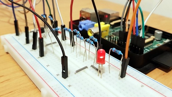
[RhinoDevel] writes in to tell us about CBM Tape Pi , an open source Commodore tape drive emulator for Raspberry Pi that needs only a handful of passive components to get wired up. Even better, the project targets the older Pis that are more likely to be languishing around in the parts bin. In the video after the break, a Commodore PET can be seen happily loading content from the original Raspberry Pi with its quaint little composite video connector.
Without any special software on the Commodore itself, the project allows the user to load and save PRGs on the Pi’s SD card, as well as traverse directories. Don’t expect stellar I/O, as [RhinoDevel] notes that no fast loader is currently implemented. Of course if you’re enough of a devotee to still be poking around a VIC-20 or C64 this far into 21st century, then we imagine you’ve got enough patience to get by.
Now is an amazing time to be involved in the hobby electronics scene. There are robots to build, cheap microcontrollers which are easy to program, and computers themselves are able to be found for very low prices. That wasn’t the case in the 1960s though, where anyone interested in “electronics” might have had a few books about ham radios or some basic circuits. If you were lucky though, you may have found a book from 1968 that outlined the construction of a digital computer made out of paperclips that [Mike Gardi] is hoping to replicate.
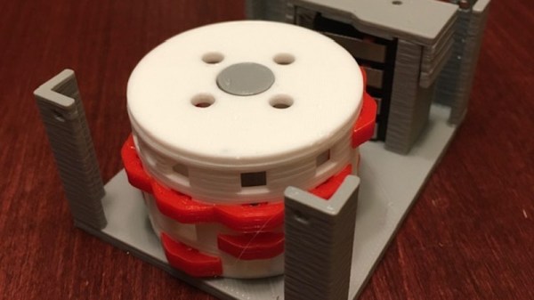
One of the first components that the book outlines is building an encoder, which can convert a decimal number to binary. In the original book the switches were made from paper clips and common household parts, but [Mike] is using a more reliable switch and some 3D prints to build his. The key of the build is the encoder wheel and pegs, which act as the “converter” between decimal and binary and actually performs the switching.
It’s a fairly straightforward build, but by working through the rest of the book the next steps are to build two binary encoders and hook all of them up to an ALU which will give him most of a working computer from long lost 1960s lore. He’s been featured recently for building other computers from this era as well.
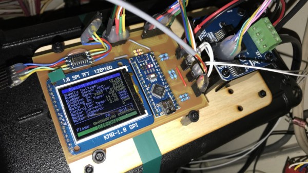
The build is based around OpenPlotter, which uses a battery of marine-ready software to handle routing charts, autopiloting, and providing a compass heading for navigation. Naturally, it all runs on a Raspberry Pi. In combination with PyPilot, it can be used to let the vessel drive itself around a series of waypoints, allowing you to soak up the atmosphere on the water without having to constantly steer the craft.
[Timo] ran into some issues, however, with the hardware side of things. Existing implementations for motor control to drive the rudder weren’t quite cutting it, so the system was reworked to run with a robust H-bridge and some fresh Arduino code. This was combined with a custom rudder sensor built with a potentiometer and some 3D printed gears. Future work aims to double up the rudder sensors for redundancy, something we should all consider at times.
Overall, the system is starting to come together, and [Timo]’s enjoying letting his boat think for itself. He notes that it’s very important to keep an eye on the boat while operating in this condition, lest it veer off course – many a boat has been lost this way. We’re always supporters of a mature attitude towards autonomous vehicle operations!
 How do you get an inkjet head on a shoe or a couch? Most printing processes require a flat surface to print. But hearkening back to the days when a blueprint was a blueprint, a mixture of an iron salt and an acid are mixed and applied to a surface an interesting reaction occurs when the surface is exposed to UV light. The chemicals react to form, of all things, prussian blue. After the reaction occurs simply washing away the remaining chemicals leaves a stable print behind.