Tables Are Turned As Robots Assemble IKEA Furniture

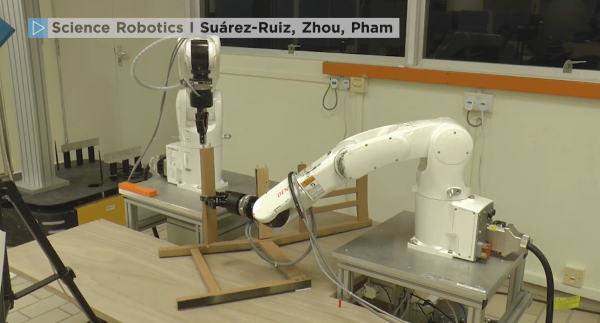
Hackaday pages are rife with examples of robots being built with furniture parts. In this example, the tables are turned and robots are the masters of IKEA pieces. We are not silly enough to assume that these robots unfolded the instructions, looked at one another, scratched their CPUs, and began assembling. Of course, the procedure was preordained by the programmers, but the way they mate the pegs into the ends of the cross-members is a very human thing to do. It reminds us of finding a phone charging socket in the dark. This kind of behavior is due to force feedback which tell the robots when a piece is properly seated which means that they can use vision to fit the components together without sub-millimeter precision.

All the hardware used to make the IKEA assembler is publicly available, and while it may be out of the typical hacker price range, this is a sign of the times as robots become part of the household. Currently, the household robots are washing machines, smart speakers, and 3D printers. Ten years ago those weren’t Internet connected machines so it should be no surprise if robotic arms join the club of household robots soon. Your next robotics project could be the tipping point that brings a new class of robots to the home.

Back to our usual hijinks, here is a robot arm from IKEA parts and a projector built into a similar lamp. or a 3D printer enclosed in an IKEA cabinet for a classy home robot.

Continue reading “Tables Are Turned As Robots Assemble IKEA Furniture”

Hybrid Lab Power Supply From Broken Audio Amp

The lab power supply is an essential part of any respectable electronics workbench. However, the cost of buying a unit that has all the features required can be eye-wateringly high for such a seemingly simple device. [The Post Apocalyptic Inventor] has showed us how to build a quality bench power supply from the guts of an old audio amplifier.

We’ve covered our fair share of DIY power supplies here at Hackaday, and despite this one being a year old, it goes the extra mile for a number of reasons. Firstly, many of the expensive and key components are salvaged from a faulty audio amp: the transformer, large heatsink and chassis, as well as miscellaneous capacitors, pots, power resistors and relays. Secondly, this power supply is a hybrid. As well as two outputs from off-the-shelf buck and boost converters, there is also a linear supply. The efficiency of the switching supplies is great for general purpose work, but having a low-ripple linear output on tap for testing RF and audio projects is really handy.

The addition of the linear regulator is covered in a second video, and it’s impressively technically comprehensive. [TPAI] does a great job of explaining the function of all the parts which comprise his linear supply, and builds it up manually from discrete components. To monitor the voltage and current on the front panel, two vintage dial voltmeters are used, after one is converted to an ammeter. It’s these small auxiliary hacks which make this project stand out – another example is the rewiring of the transformer secondary and bridge rectifier to obtain a 38V rail rated for twice the original current.

The Chinese DC-DC switching converters at the heart of this build are pretty popular these days, in fact we’re even seeing open source firmware being developed for them. If you want to find out more about how they operate on a basic level, here’s how a buck converter works, and also the science behind boost converters.

Continue reading “Hybrid Lab Power Supply From Broken Audio Amp”

The Colpitts Oscillator Explained

The Colpitts oscillator is a time-tested design — from 1918. [The Offset Volt] has a few videos covering the design of these circuits including an op-amp and a transistor version. You can find the videos below.

You can tell a Colpitts oscillator by the two capacitors in the feedback circuit. The capacitors form an effective capacitance for the circuit (assuming you have C1 and C2) of the product of C1 and C2 divided by the sum of the two capacitors. The effective capacitance and the inductance form a bandpass filter that is very sharp at the frequency of interest, allowing the amplifier to build up oscillations at that frequency.

Continue reading “The Colpitts Oscillator Explained”

Raytheon’s Analog Read-Only Memory Is Tube-Based

There are many ways of storing data in a computer’s memory, and not all of them allow the computer to write to it. For older equipment, this was often a physical limitation to the hardware itself. It’s easier and cheaper for some memory to be read-only, but if you go back really far you reach a time before even ROMs were widespread. One fascinating memory scheme is this example using a vacuum tube that stores the characters needed for a display.

[eric] over at TubeTime recently came across a Raytheon monoscope from days of yore and started figuring out how it works. The device is essentially a character display in an oscilloscope-like CRT package, but the way that it displays the characters is an interesting walk through history. The monoscope has two circuits, one which selects the character and the other determines the position on the screen. Each circuit is fed a delightfully analog sine wave, which allows the device to create essentially a scanning pattern on the screen for refreshing the display.

[eric] goes into a lot of detail on how this c.1967 device works, and it’s interesting to see how engineers were able to get working memory with their relatively limited toolset. One of the nice things about working in the analog world, though, is that it’s relatively easy to figure out how things work and start using them for all kinds of other purposes, like old analog UHF TV tuners.

Arduino Watchdog Sniffs Out Hot 3D Printers

We know we’ve told you this already, but you should really keep a close eye on your 3D printer. The cheaper import machines are starting to display a worrying tendency to go up in flames, either due to cheap components or design flaws. The fact that it happens is, sadly, no longer up for debate. The best thing we can do now is figure out ways to mitigate the risk for all the printers that are already deployed in the field.

At the risk of making a generalization, most 3D printer fires seem to be due to overheating components. Not a huge surprise, of course, as parts of a 3D printer heat up to hundreds of degrees and must remain there for hours and hours on end. Accordingly, [Bin Sun] has created a very slick device that keeps a close eye on the printer’s temperature at various locations, and cuts power if anything goes out of acceptable range.

The device is powered by an Arduino Nano and uses a 1602 serial LCD and KY040 rotary encoder to provide the user interface. The user can set the shutdown temperature with the encoder knob, and the 16×2 character LCD will give a real-time display of current temperature and power status.

Once the user-defined temperature is met or exceeded, the device cuts power to the printer with an optocoupler relay. It will also sound an alarm for one minute so anyone in the area will know the printer needs some immediate attention.

We’ve recently covered a similar device that minimizes the amount of time the printer is powered on, but checking temperature and acting on it in real-time seems a better bet. No matter what, we’d still suggest adding a smoke detector and fire extinguisher to your list of essential 3D printer accessories.

Continue reading “Arduino Watchdog Sniffs Out Hot 3D Printers”

Buttery Smooth Fades With The Power Of HSV

In firmware-land we usually refer to colors using RGB. This is intuitively pleasing with a little background on color theory and an understanding of how multicolor LEDs work. Most of the colorful LEDs we are use not actually a single diode. They are red, green, and blue diodes shoved together in tight quarters. (Though interestingly very high end LEDs use even more colors than that, but that’s a topic for another article.) When all three light up at once the emitted light munges together into a single color which your brain perceives. Appropriately the schematic symbol for an RGB LED without an onboard controller typically depicts three discrete LEDs all together. So it’s clear why representing an RGB LED in code as three individual values {R, G, B} makes sense. But binding our representation of color in firmware to the physical system we accidentally limit ourselves.

The inside of an RGB LED

Last time we talked about color spaces, we learned about different ways to represent color spatially. The key insight was that these models called color spaces could be used to represent the same colors using different groups of values. And in fact that the grouped values themselves could be used to describe multidimensional spacial coordinates. But that post was missing the punchline. “So what if you can represent colors in a cylinder!” I hear you cry. “Why do I care?” Well, it turns out that using colorspace can make some common firmware tasks easier. Follow on to learn how!

Continue reading “Buttery Smooth Fades With The Power Of HSV”

Watch The World Spin With The Earth Clock

With the June solstice right around the corner, it’s a perfect time to witness first hand the effects of Earth’s axial tilt on the day’s length above and beyond 60 degrees latitude. But if you can’t make it there, or otherwise prefer a more regular, less deprived sleep pattern, you can always resort to simulations to demonstrate the phenomenon. [SimonRob] for example built a clock with a real time rotating model of Earth to visualize its exposure to the sun over the year.

The daily rotating cycle, as well as Earth’s rotation within one year, are simulated with a hand painted plastic ball attached to a rotating axis and mounted on a rotating plate. The hand painting was done with a neat trick; placing printed slivers of an atlas inside the transparent orb to serve as guides. Movement for both axes are driven by a pair of stepper motors and a ring of LEDs in the same diameter as the Earth model is used to represent the Sun. You can of course wait a whole year to observe it all in real time, or then make use of a set of buttons that lets you fast forward and reverse time.

Earth’s rotation, and especially countering it, is a regular concept in astrophotography, so it’s a nice change of perspective to use it to look onto Earth itself from the outside. And who knows, if [SimonRob] ever feels like extending his clock with an aurora borealis simulation, he might find inspiration in this northern lights tracking light show.

This is a spectacular showpiece and a great project you can do with common tools already in your workshop. Once you’ve mastered earth, put on your machinists hat and give the solar system a try.