Everyone Should Build At Least One Regenerative Radio Receiver

When we build an electronic project in 2016, the chances are that the active components will be integrated circuits containing an extremely large amount of functionality in a small space. Where once we might have used an op-amp or two, a 555 timer, or a logic gate, it’s ever more common to use a microcontroller or even an IC that though it presents an analog face to the world does all its internal work in the digital domain.

Making A Transistor Radio, 2nd edition cover. Fair use, via Internet Archive.

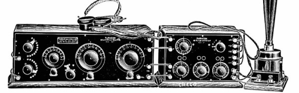
There was a time when active components such as tubes or transistors were likely to be significantly expensive, and integrated circuits, if they even existed, were out of the reach of most constructors. In those days people still used electronics to do a lot of the same jobs we do today, but they relied on extremely clever circuitry rather than the brute force of a do-anything super-component. It was not uncommon to see circuits with only a few transistors or tubes that exploited all the capabilities of the devices to deliver something well beyond that which you might expect.

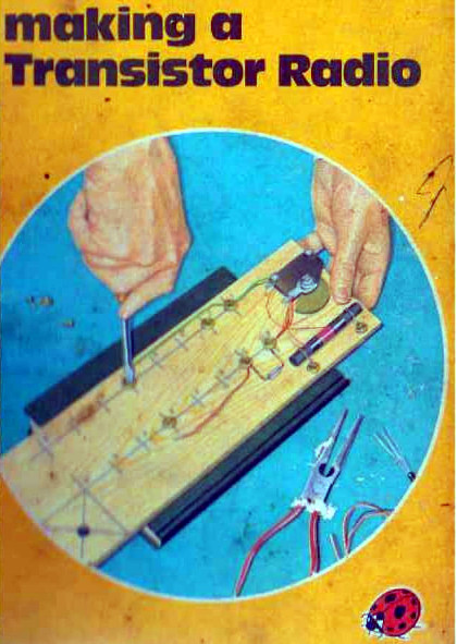
One of the first electronic projects I worked on was just such a circuit. It came courtesy of a children’s book, one of the Ladybird series that will be familiar to British people of a Certain Age: [George Dobbs, G3RJV]’s Making A Transistor Radio. This book built the reader up through a series of steps to a fully-functional 3-transistor Medium Wave (AM) radio with a small loudspeaker.

Two of the transistors formed the project’s audio amplifier, leaving the radio part to just one device. How on earth could a single transistor form the heart of a radio receiver with enough sensitivity and selectivity to be useful, you ask? The answer lies in an extremely clever circuit: the regenerative detector. A small amount of positive feedback is applied to an amplifier that has a tuned circuit in its path, and the effect is to both increase its gain and narrow its bandwidth. It’s still not the highest performance receiver in the world, but it’s astoundingly simple and in the early years of the 20th century it offered a huge improvement over the much simpler tuned radio frequency (TRF) receivers that were the order of the day.

Continue reading “Everyone Should Build At Least One Regenerative Radio Receiver”

ENIAC: The Way We Were

When I first got interested in computers, it was all but impossible for an individual to own a computer outright. Even a “small” machine cost a fortune not to mention requiring specialized power, cooling, and maintenance. Then there started to be some rumblings of home computers (like the Mark 8 we recently saw a replica of) and the Altair 8800 burst on the scene. By today’s standards, these are hardly computers. Even an 8-bit Arduino can outperform these old machines.

As much disparity as there is between an Altair 8800 and a modern personal computer, looking even further back is fascinating. The differences between the original computers from the 1940s and anything even remotely “modern” like an Altair or a PC are astounding. If you are interested in that kind of history, you should read a paper entitled “Electronic Computing Circuits of the ENIAC” by [Arthur W. Burks].

These mid-century designers used tubes and were blazing new ground. Part of what makes the ENIAC so different is that it had a different design principle than a modern computer. It was less a general purpose stored-program computer and more of a collection of logic circuits that could be configured to solve problems — sort of a giant vacuum tube FPGA, if you will. It used some internal representations that proved to be suboptimal which also makes it seem strange. The EDSAC — a later device — was closer to what we think of as a computer. Yet the ENIAC was a major step in the direction of a practical digital computer.

Cost and Size

eniac
Programming the ENIAC in 1951 (±4 years)
[Image Source: Public Domain]
The size of ENIAC is hard to imagine. The device had about 18,000 tubes, 7,000 diodes, 70,000 resistors, 10,000 capacitors, and 6,000 switches. There were 5 million hand-soldered joints! ([Thomas Haigh] tells us that while this is widely reported, the real number was about 500,000.) Physically, it stood 10 feet tall, 3 feet deep, and 100 feet long. The tube filaments alone required 80 kW of power. Even the cooling system consumed 20 kW. In total, it took 150 kW to run the beast.

The cost of the machine was about $487,000. Almost a half-million dollars in 1946 is plenty. But that’s nearly seven million dollars in today’s money. What was worth that kind of expenditure? The military built firing tables for shell trajectories. From the [Burks] paper:

“A skilled computer with a desk machine can compute a 60-second trajectory in about twenty hours…”

Keep in mind that in 1946, a computer was a person. [Burks] goes on to say that a differential analyzer can do the same job in 15 minutes. ENIAC, on the other hand, could do it in 30 seconds and with a greater precision than the differential analyzer.

Continue reading “ENIAC: The Way We Were”

Get To Know 3½ Digit ADCs With The ICL71xx

Riffling through my box of old projects, I came upon a project that I had built in the 80’s — an Automotive Multimeter which was published in the Dutch/British Elektor magazine. It could measure low voltage DC, high current DC, resistance, dwell angle, and engine RPM and ran off a single 9V battery. Besides a 555 IC for the dwell and RPM measurement and a couple of CMOS gate chips, the rest of the board is populated by a smattering of passives and a big, 40 pin DIP IC under the 3½ digit LCD display. I dug some more in my box, and came up with another Elektor project from back then — a True RMS digital Wattmeter with a 3½ digit LCD display that could measure up to 2kW. It had the same chip too. Some more digging, and I found a digital panel meter. This had a 7 segment LED display, but the chip was again from the same family.

ICL7107 LED version
ICL7107 LED version

Look under the hood of any device with a 3½ or 4½ digit, 7 segment, LCD or LED from the ’80’s or ’90’s and you will likely spot this 40-pin DIP with the Intersil logo (although it was later also manufactured by many other fabs; Harris and Maxim among others). The chip doing all the heavy-lifting was likely to be the ICL7106 or ICL7107. These devices were described as high performance, low power, 3½ digit A/D converters containing seven segment decoders, display drivers, voltage reference and clock. In short, everything you needed to take a DC analog signal and display it. Over time, a whole series of devices were spawned:

  • 7106 – 3½ digit, 7 segment LCD
  • 7107 – 3½ digit, 7 segment LED
  • 7116 – 3½ digit, 7 segment LCD, with display HOLD (freeze)
  • 7117 – 3½ digit, 7 segment LED, with display HOLD (freeze)
  • 7126 – improved 7106
  • 7136 – improved 7126
  • 7135 – 4½ digit, 7 segment LCD

There were many similar devices available, but the ICL71xx series was by far one of the most popular, due to its easy of use, low parts count and single chip implementation. Here are several parts (linking to PDF datasheets) to illustrate my point: the TC14433/A needed several peripheral devices, ES5107 (a clone of a clone — read below), CA3162 (which has BCD output, and needs the CA3161 or similar to interface to a display), or the AD2020 (which too needed a lot of support circuitry).

The ICL71xx was the go-to device for a reason. Let’s take a look at the engineering and business behind this fascinating chip.

Continue reading “Get To Know 3½ Digit ADCs With The ICL71xx”

Fixing My 4×4: The Battle Of The Bent Valves

If you know me at all, you know I’m a car guy. I’m pretty green as far as hardcore wrenching skills go, but I like to tackle problems with my vehicles myself – I like to learn by doing. What follows is the story of how I learned a few hard lessons when my faithful ride died slowly and painfully in my arms over the final months of 2016.

For context, my beast of a machine was a 1992 Daihatsu Feroza. It’s a 4WD with a 1.6 litre fuel injected four-cylinder engine. It had served me faithfully for over a year and was reading around 295,000 kilometers on the odometer. But I was moving house and needed to pull a trailer with all my possessions on an 800 km journey. I didn’t want to put the stress on the car but I didn’t have a whole lot of choice if I wanted to keep my bed and my prized Ricoh photocopier. I did my best to prepare the car, topping up the oil which had gotten perilously low and fitting new tyres. I’d had a hell of a time over the winter aquaplaning all over the place and wasn’t in the mood for a big ugly crash on the highway. Continue reading “Fixing My 4×4: The Battle Of The Bent Valves”

Increase The Range Of An ESP8266 With Duct Tape

For the longest time now, I’ve wanted to build a real, proper radio telescope. To me, this means a large parabolic reflector, a feed horn made of brass sheet, coat hanger wire, and at least for the initial experiments, an RTL-SDR dongle. I’ve done the calculations, looked at old C-band antennas on Craigslist, and even designed a mount or two that would make pointing the dish possible. I’ve done enough planning to know the results wouldn’t be great. After months of work, the best I could ever hope for is a very low-resolution image of the galactic plane. If I get lucky, there might be a bright spot corresponding to Sagittarius A.

There are better ways to build a radio telescope in your back yard, but the thought of having a gigantic parabolic dish out back, peering into the heavens, has stuck with me. I’ve even designed a dish that can be taken apart easily and transported because building your own dish is far cooler than buying a West Virginia state flower from a guy on Craigslist.

Recently, I was asked to come up with a futuristic, space-ey prop for an upcoming video. My custom-built, easily transportable parabolic antenna immediately sprang to mind. The idea of a three-meter diameter parabolic dish was rejected for something a little more practical and a little less expensive, but I did go so far as to do a few more calculations, open up a CAD program, and start work on the actual design. As a test, I decided to 3D print a small model of this dish. In creating this model, I inadvertently created the perfect WiFi antenna for an ESP8266 module using nothing but 3D printed parts, a bit of epoxy, and duct tape.

Continue reading “Increase The Range Of An ESP8266 With Duct Tape”

Let’s Prototype! This Filament End Needs 80 Decibels

Reaching the end of a spool of filament when 3D printing is inevitable. The result ranges from minor annoyance to ruined print. Recently, I needed to print a number of large jobs that used just over half a spool of plastic each. Unwilling to start every print with a fresh spool (and shelve a 60% used one afterward), I had a problem to solve. What my 3D printer needed was filament monitor, or at least that’s what I thought.

After reviewing some projects and aftermarket options, I ended up making my own. Like most prototypes, it wasn’t an instant success, but that’s fine. One of the goals of prototyping is not only to validate that the problems you’re solving are the same ones you think exist, but also to force other problems and issues you may not have considered to the surface. Failure is only a waste if nothing is learned, and the faster and cheaper that learning happens, the better.

Sensible design steps also help minimize waste, so I started by looking at what kind of solutions already existed.

Continue reading “Let’s Prototype! This Filament End Needs 80 Decibels”

PCB Design Guidelines To Minimize RF Transmissions

There are certain design guidelines for PCBs that don’t make a lot of sense, and practices that seem excessive and unnecessary. Often these are motivated by the black magic that is RF transmission. This is either an unfortunate and unintended consequence of electronic circuits, or a magical and useful feature of them, and a lot of design time goes into reducing or removing these effects or tuning them.

You’re wondering how important this is for your projects and whether you should worry about unintentional radiated emissions. On the Baddeley scale of importance:

  • Pffffft – You’re building a one-off project that uses battery power and a single microcontroller with a few GPIO. Basically all your Arduino projects and around-the-house fun.
  • Meh – You’re building a one-off that plugs into a wall or has an intentional radio on board — a run-of-the-mill IoT thingamajig. Or you’re selling a product that is battery powered but doesn’t intentionally transmit anything.
  • Yeeeaaaaahhhhhhh – You’re selling a product that is wall powered.
  • YES – You’re selling a product that is an intentional transmitter, or has a lot of fast signals, or is manufactured in large volumes.
  • SMH – You’re the manufacturer of a neon sign that is taking out all wireless signals within a few blocks.

Continue reading “PCB Design Guidelines To Minimize RF Transmissions”