The C.H.I.P. from Next Thing Co. bills itself as the world’s first nine dollar computer. That’s not a lie; their Kickstarter took in over two million dollars for a tiny single board computer with composite Video, WiFi, Bluetooth 512MB of RAM, 4GB of storage, and a 1GHz CPU. That’s a complete computer, sans keyboard, mouse, and monitor. You won’t get that with the $35 Raspberry Pi – you’ll need to add a WiFi adapter and an SD card for the same functionality – and you won’t get that with any other single board computer.
Understandably, the C.H.I.P. is already extremely successful. The company behind it has about 50,000 pre-orders, and people lined up to wait until well into next year for this computer. Exactly how Next Thing Co. managed to build a single board computer and send it out the door for nine dollars is a question that has yet to be answered, and is leaving more than a few people puzzled.
The Olimex blog has given their opinion of the C.H.I.P, and if that’s to be believed, the news isn’t good. The guys at Olimex know their stuff when it comes to making cheap single board computers; they have more than a few for sale, and they know what the Flash and DRAM market is like. To them, it’s impossible to sell a computer like the C.H.I.P. at $9. A quote from Allwinner for a similar module is $16 at the quantity Next Thing Co. would be looking at. That’s just the module with RAM and Flash – no Wifi, no board, no connectors. How could it be possible to sell this computer for only $9?
We’ve been admirers of the work [Eric] and friends have been doing over at TubeTime for years. One of the earliest we can remember is the decatron kitchen timer, and we still tell the story of [Eric] purposely leaving out button debouncing in order to make his vector flappy bird even harder.
TubeTime is back at it this year and we had the opportunity to speak with them at Bay Area Maker Faire. The group specializes in working with old tube displays and this year’s offering was spectacular in many ways. First off, the software side of things is an emulator running on an STM32 F4 Discovery board. The chips on these boards have a pair of 12-bit DACs which are driving the X and Y of the vector displays. Code to run the original ROMs was ported from existing projects, but the audio for the games was kind of a hack to get working.
This particular display is where things get really fascinating. The tube itself was originally manufactured as test equipment for television repairmen. What’s fascinating about this is that [Eric] had to rewind the deflection yokes himself to get it working again. Luckily he documented quite a bit about his initial research into this process and his experiments to remedy some distortion issues he encountered once it was working.
Make sure to head on over to TubeTime and read their overview of the Battlezone machine. After the break we’ve also embedded a few of our own pictures as well as the interview at BAMF.
Here’s your chance to bring some great stuff home from The Hackaday Prize. For the next 3 weeks we’ll be looking for the best entries using Atmel, Freescale, Microchip, and Texas Instruments parts.
Each of the four contests (yes, four running concurrently) will award the top 50 projects. That’s 200 in total being recognized. The odds are really in your favor — currently some of those lists have less than 50 projects on them — so enter yours right away! Scroll down to see the mountain of prizes that we have for this epic run.
Make Sure We Know About Your Entry
There are two things you need to do to be eligible for this pile of awesome stuff:
Do this by the morning of Monday, June 29th to make sure you’re in the running. We’ve been diligent about adding entries to the lists for Atmel, Freescale, Microchip, and Texas Instruments but at the rate new entries have been coming in it’s easy to miss one here or there. Don’t be bashful about asking to be added to these lists!
The prerequisite is to be using a part from one of these four manufacturers. We’ll be looking at these lists for projects using great ideas which have also been well-documented. Tells us why you’re building it, what it does, how you came up with the idea… you know, the whole story!
The Loot
DS Logic
Mooshimeter
Stickvise
Up for grabs in each of the 4 contests are:
3x Mooshimeters which is a multimeter that uses your smartphone as a wireless readout.
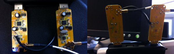
Let’s start off with proof. Below is an animation of a measurement of airplanes and meteors I made using a radar system that I built with a few simple easily available pieces of hardware: two $8 RTL software defined radio dongles that I bought on eBay, and two log-periodic antennas. And get this, the radar system you’re going to build works by listening for existing transmissions that bounce off the targets being measured!
I wrote about this in a very brief blog posting a few years ago. It was mainly intended as a zany little side story for our radio telescope blog, but it ended up raising a lot of interest. Because this has been a topic that keeps attracting inquiries, I’m going to explain how I did the experiment in more detail.
It will take a few posts to show how to build a radar capable of performing these types of measurements. This first part is the overview. In later postings I will go through more detailed block diagrams of the different parts of a passive radar system, provide example data, and give some Python scripts that can be used to perform passive radar signal processing. I’ll also go through strategies to determine that everything is working as expected. All of this may sound like a lot of effort, but don’t worry, making a passive radar isn’t too complicated.
Most hobbyists say that it is easier to build a functional prototype of an electronic device, than to make the enclosure for it. You could say that there are a lot of ready-made enclosures on the market, but they are never exactly what you need. You could also use a 3D printer to build a custom enclosure, but high-end 3D printers are too expensive, and the cheaper ones produce housings which are often not robust enough, and also require a lot of additional treatment.
Another way is to build the enclosure out of FR4, a material which is commonly used in PCB production. Such enclosures are low-cost, with thin walls but yet very strong, nice looking, pleasant to the touch and have excellent thermal and moisture stability. FR4 offers some more possibilities – efficient wiring with no wires inside the housing, integrated UHF or SHF antennas or RFID coils, capacitive switches, electrical shielding, selective semi-transparency, water or air tightness, and even integration of complex mechanical assemblies.
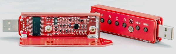
Here I shall explain the process of building those “magic” enclosures. It is based on nearly fifty years of personal experience and more than a hundred enclosures, built for most of my projects. Here are two examples – this case for a hardware password manager is just a few centimeters long, while the other one (protective transportation cover for my son’s synthesizer) measures 125cm (about 49 inches), and yet both of them are strong enough to withstand a grown man standing on top of them.
The global approach is simple – you take the sheet of single-sided copper clad FR4, cut it and solder the parts together. That sounds simple, but there are a lot of details which should be met if you want to get top results. Please read about them carefully. You might be tempted to skip some of the steps described here, but if you do so, you will most likely end up being disappointed with the results.
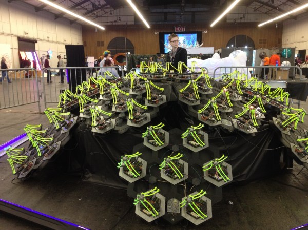
For a few years now I’ve been developing an interactive army of delta robots. This ongoing project is fueled by my desire to control many mechanical extremities like an extension of my body (I’m assuming I’m not the only one who fantasizes about robots here).
Since my army doesn’t have a practical application… other than producing pretty light patterns and making the user feel extremely cool for a minute, I guess you’d call it art. In the past I’ve held a Kickstarter to fund the production of my art which I can now happily show at cool events with interesting people; Maker Faire being one of them.
Interactivity and Sprawling Crowds
Last year, for our debut at the big Bay Area Maker Faire, my collaborator, [Mark], and I displayed a smaller sampling of 30 robots for our installation. We also decided to create an interactive aspect for others to experience. After the end of our crowdfunding period last March, we had a little over a month to do any development before the big event, so our options were slim. The easy solution was to jam our delta code into the hand tracking demo which comes with the Xbox Kinect’s Open NI within Processing. This was cool enough to exhibit, but we hadn’t really anticipated how it would go over in an environment as densely packed as the dark room at Maker Faire.
We should have known better. Both of us were aware that there would be many, many children… all with micro hands to confuse and bewilder the Kinect, but we did it anyway. Our only resolve was to implement the feature that would force the Kinect to track one hand at a time, only after being waved at in a very particular fashion. After needing to explain this stipulation to every person who stopped by our booth over the course of the weekend, we decided never to use the Kinect for crowds ever again; lesson learned.
Delta Robots and DMX
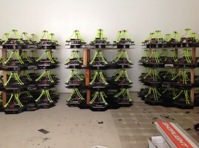
Over the past year since that experience, we’ve tripled the size of the installation and brainstormed some better demo ideas. As of now, the robots are all individually addressable over an RS485 bus, and we use the DMX protocol over a CAT5 cable to send commands. If you aren’t familiar with it, DMX is used in show production to control stage lighting… to which there is a super neat and free application called QLC+ that allows you to effectively orchestrate the motion and color of many individual light units; perfect for our cause.
Functionally, each of the 84 delta robots in the installation believes that it is a stage light (robots with identity issues). We mapped the X and Y axis of the end effector to the existing pan and tilt values, and the z axis to the beam focus value. The RGB of the LED mounted in the end effector of each delta maps directly to the RGB value of the stage light.
By using the sliders in the QLC+ GUI, I could select groups of robots and create presets for position and color. This was great, someone like me who doesn’t really write a lot of code could whip up impressive choreography with little sweat. Additionally, the program comes with a nice visualizer, where you can layout virtual nodes and view your effects as you develop them.
This is the layout of our installation mapped in QLC+. The teal and purple sliders around each light represent pan and tilt (or in our case X and Y):
Lighting control was an interesting solution. Having autonomous robots this year changed how people responded to them, as they were less like an army you’d command and more of a hypnotic field of glowing grass.
[Mark] and I are considering picking up some flex sensors and maybe playing with the Leap or an EEG headset as a means to reintroduce the interactive aspect. Bottom line, I have this cool new toy that I can’t wait to play with over the summer!
I usually see retro-gaming projects using tiny screens with a fair number of pixels (64×64) but what I really like is the look of making every pixel count. With this in mind I built 1-Pixel Pac-Man, the classic coin-op experience but with characters that consist of just one pixel. Playing a throw-back like this wouldn’t be the same without some vintage controls so I picked up an Atari joystick, patched it into a microcontroller, and started coding. Check it out:
Smartmatrix Bundle
32×32 RGB panel with acrylic diffuser
Back of the Smartmatrix
This piece of hardware made the project build really easy: the Smartmatrix. [Louis Beaudioin] developed the Smartmatrix and it’s been in the Hackaday Store for a while now. The display module itself is a commodity item that is used in LED billboards. There are shrouded headers on the back of the panels, to the left and right sides, which allow them to be daisy chained. The Smartmatrix PCB plugs into one of these shields, provides a soldering footprint for the Teensy 3.1 which drives the display, and gives you the wiring to connect screw terminals from the PCB to the power terminals on the module. Why the need for beefy power jumpers? At full white the thing can draw about 3.5A — don’t worry there’s a power supply included in the bundle.
Also integral to making this look good is the diffuser panel which is frosted acrylic. The Smartmatrix is designed to be housed in a shadowbox frame; it even includes a frame backer board with a cut-out for the Teensy 3.1 so it can be programmed without opening the thing up. I like looking at the guts so I’m leaving my free floating until I come up with an interesting way to mount everything as one unit.
Programming Pac-Man from the Ground Up
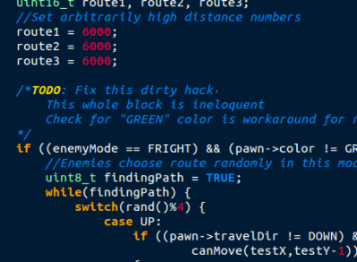
If you haven’t looked into it before, the ghost AI and gameplay details for Pac-Man are absolutely brilliant. [Toru Iwatani] did a masterful job with the original, and you should take a look at all of the analysis that has been done over the years. The best collection I could find was the Pac-Man Dossier and I based most of my code on the rules described there.
Basically the ghosts have two modes, chase and scatter. The modes set the enemy targets differently; to points at the four corners of the board in scatter, and to points relative to the player in chase. The relative part is key; only the red enemy actually chases you. Another one of them looks at the red enemy’s distance and angle, and targets the reflection of that vector. Really easy, really clever, and results in enemy behavior that’s believable. It isn’t just the enemy movement, little touches like a speed penalty (1/60 of a second) for each dot the player gobbles up means the enemies can catch up if you continuously eat, but you can escape by taking the path already-eaten.
Library, DMA, and Extra Hardware
Teensy 3.1
DB9 Connector for Joystick
Extras in the Bundle
Kickstarter remote and RTC Module
The hardware and software running the Smartmatrix made the display portions of the project really simple. First off, the Teensy 3.1 is fast, running at 96MHz in this case. Second, it has Direct Memory Access (DMA) which [Louis] used in the Smartmatrix library. This means that driving the display takes almost no CPU time at all, leaving the rest for your own use. This example of a game is under-utilizing this power… it’s totally capable of full-motion video and calculating amazing visualizations on the fly.
The PCB hosting the Teensy 3.1 breaks out several pins to one side. I’m not sure what I’ll add in the future so I actually used the extra surface-mount IO pins on the bottom of the Teensy to connect the Atari joystick (which is simply a set of switches). The are enough pads for two joysticks so I used pin sockets to interface the Teensy to the PCB so that I can get to it again later.
The kit also includes an IR receiver and remote, and also a microSD card to loading animations (there’s an SD socket on the PCB). The bundle in the Hackaday Store is a kit you solder yourself, but [Louis’] company, Pixelmatix, has a Kickstarter running for fully-assembled versions that come with a black remote and sound-visualization hardware.
Future Improvements
The game is fully working, but there are a few key things that I really want to add. The Teensy 3.1 has a single DAC pin available. I’m fairly certain the original coin-op game had mono audio. It should be possible to reproduce the sound quite accurately with this board. That would really make the project pop.
There are also a bunch of touch-ups that need to happen. I’d like to add an animation when the player is eaten by an enemy, and a countdown before the level restarts. The score, shown in binary on the right column, should be scrolled out in decimal when the game ends, and what’s a coin-op recreation without a high-score screen?


 Since my army doesn’t have a practical application… other than producing pretty light patterns and making the user feel extremely cool for a minute, I guess you’d call it art. In the past I’ve held a
 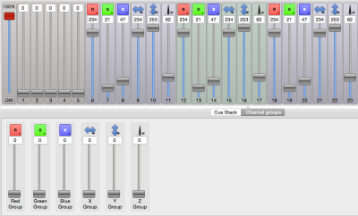 Functionally, each of the 84 delta robots in the installation believes that it is a stage light (robots with identity issues). We mapped the X and Y axis of the end effector to the existing pan and tilt values, and the z axis to the beam focus value. The RGB of the LED mounted in the end effector of each delta maps directly to the RGB value of the stage light.