Richard Feynman: A Life Of Curiosity And Science

It was World War II and scientists belonging to the Manhattan Project worked on calculations for the atomic bomb. Meanwhile, in one of the buildings, future Nobel Prize winning theoretical physicist Richard Feynman was cracking the combination lock on a safe because doing so intrigued him. That’s as good a broad summary of Feynman as any: scientific integrity with curiosity driving both his work and his fun.

If you’ve heard of him in passing it may be because of his involvement on the Space Shuttle Challenger disaster commission or maybe you’ve learned something from one of his many lectures preserved on YouTube. But did you know he also played with electronics as a kid, and almost became an electrical engineer?

He was the type of person whom you might sum up by saying that he had an interesting life. The problem is, you have to wonder how he fit it all into one lifetime, let alone one article. We’ll just have to let our own curiosity pick and choose what to say about this curious character.

Continue reading “Richard Feynman: A Life Of Curiosity And Science”

The Electrical Outlet And How It Got That Way

Right now, if you happen to be in Noth America, chances are pretty good that there’s at least one little face staring at you. Look around and you’ll spy it, probably about 15 inches up from the floor on a nearby wall. It’s the ubiquitous wall outlet, with three holes arranged in a way that can’t help but stimulate the facial recognition firmware of our mammalian brain.

No matter where you go you’ll find those outlets and similar ones, all engineered for specific tasks. But why do they look the way they do? And what’s going on electrically and mechanically behind that familiar plastic face? It’s a topic we’ve touched on before with Jenny List’s take on international mains standards. Now it’s time to take a look inside the common North American wall socket, and how it got that way.

Continue reading “The Electrical Outlet And How It Got That Way”

Hackaday Links Column Banner

Hackaday Links: May 13, 2018

The dumbest thing this week is Uber’s flying car concept of the future. The braintrust at Uber envisions a world of skyports, on rooftops or on the ground that will handle 200 takeoffs and landings per hour. That is 4800 per day at a maximum. The record for the number of total takeoffs and landings for any airport was set last year at Mumbai’s Chhatrapati Shivaji airport with 969 takeoffs and landings in a twenty-four hour period. Yes, Uber wants to put the world’s busiest airport in a parking lot or something. Just wait, it gets dumber. Uber’s ‘flying car’ looks like a standard quadcopter, but with stacked, non-contrarotating props, for safety. These aircraft will be powered electrically, although it’s not quite clear if this is a hybrid setup (which could actually be practical now, but without regulatory precedent) or something built around an enormous battery (impractical for anything bigger than a 152 in this decade).

This aircraft is just a render, and Uber expects it to be certified for commercial flight in two to five years. This is nearly impossible. Uber plans to fly these aircraft autonomously. This will never happen. Additionally, Uber will not manufacture or design the aircraft. Instead, they will partner with a company that has experience in aerospace — Bell or Embraer, for instance — making the render a moot point, because ultimately Uber is just going to go with whatever Bell or Embraer have on the drawing board. Uber’s entire business plan is “move fast and break laws”, which will not serve them well with the FAA. The mere mention of Uber’s self-flying car has lowered the level of public discourse and has made us all dumber.

Here’s a great example of how cheap TVs are getting. [tmv22] built a 55 inch, 4k digital photo frame for $400. The TV was one Walmart was blowing out for two hundred and sixty dollars. Add in an Odroid C2 and some various cables and hardware, and you have an absurd digital photo frame for a few benjamins.

Espressif is getting investment from Intel’s venture capital division. Espressif, is, of course, the company behind the incredibly popular ESP8266 and ESP32 chipsets designed for the Internet of Things. Before the ESP8266 module popped up for sale on SeeedStudios, no one had heard of Espressif. Intel, on the other hand, is the largest semiconductor company on the planet and recently exited the maker IoT space because of the complete and utter failure of the Curie, Joule, Edison, and Galileo product lines. I would bet a significant portion of Intel’s failure was due to their inability to release datasheets.

Awesome news for synth heads. Behringer is cloning just about every classic synth and drum machine. At Superbooth 2018, Behringer, manufacturers of the worst mixers on the planet, revealed their clone of the Roland SH-101 synthesizer. It’s called the MS-101, and yes, it has the keytar grip. Also announced is a clone of the TR-808, Odyssey One, the OB-Xa, Arp 2600, and M100 modules. Here’s some context for you: a good Detroit techno show consists of an SH-101, TB-303, TR-808 and TR-909, all made by Roland in the 80s. These vintage synths and drum machines, at current prices, would cost about $10,000, used. The prices for these clone synths haven’t been announced, but we’re looking at a Detroit techno show for $1000. That’s nuts. Here’s a video of the 808.

Biasing That Transistor: The Common Base Amplifier

We’ve previously remarked upon a generation lucky enough to be well-versed in microcontrollers and computersised electronics through being brought up on the Arduino or the Raspberry Pi but unlucky enough to have missed out on basic electronics such as how to bias a transistor, and to address that gap we’ve taken a look at the basics of transistor biasing.

All the circuits we worked with in the previous article had the transistor’s emitter taken to ground, took their input from the base, and their output from the collector. This configuration, called a Common Emitter amplifier is probably the most common, but it is far from the only way to use a transistor. Once you have set up the bias voltage as we described to the point at which the transistor is in its linear region, there are several other ways in which the device can be used as an amplifier. The subject of this article is one of these configurations, so described because it takes the transistor’s base to the ground instead of the emitter, as a Common Base amplifier. Continue reading “Biasing That Transistor: The Common Base Amplifier”

Fail Of The Week: 3D Printed Worm Gear Drive Project Unveils Invisible Flaw

All of us would love to bring our projects to life while spending less money doing so. Sometimes our bargain hunting pays off, sometimes not. Many of us would just shrug at a failure and move on, but that is not [Mark Rehorst]’s style. He tried to build a Z-axis drive for his 3D printer around an inexpensive worm gear from AliExpress. This project was doomed by a gear flaw invisible to the human eye, but he documented the experience so we could all follow along.

We’ve featured [Mark]’s projects for his ever-evolving printer before, because we love reading his well-documented upgrade adventures. He’s not shy about exploring ideas that run against 3D printer conventions, from using belts to drive the Z-axis to moving print cooling fan off the print head (with followup). And lucky for us, he’s not shy about document his failures alongside the successes.

He walks us through the project, starting from initial motivation, moving on to parts selection, and describes how he designed his gearbox parts to work around weaknesses inherent to 3D printing. After the gearbox was installed, the resulting print came out flawed. Each of the regularly spaced print bulge can be directly correlated to a single turn of the worm gear making it the prime suspect. Then, to verify this observation more rigorously, Z-axis movement was measured with an indicator and plotted against desired movement. If the problem was caused by a piece of debris or surface damage, that would create a sharp bump in the plot. The sinusoidal plot tells us the problem is more fundamental than that.

This particular worm gear provided enough lifting power to move the print bed by multiplying motor torque, but it also multiplied flaws rendering it unsuitable for precisely positioning a 3D printer’s Z-axis. [Mark] plans to revisit the idea when he could find a source for better worm gears, and when he does we’ll certainly have the chance to read what happens.

Optocouplers: Defending Your Microcontroller, MIDI, And A Hot Tip For Speed

Deep in the heart of your latest project lies a little silicon brain. Much like the brain inside your own bone-plated noggin, your microcontroller needs protection from the outside world from time to time. When it comes to isolating your microcontroller’s sensitive little pins from high voltages, ground loops, or general noise, nothing beats an optocoupler. And while simple on-off control of a device through an optocoupler can be as simple as hooking up an LED, they are not perfect digital devices.

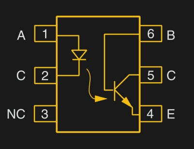
But first a step back. What is an optocoupler anyway? The prototype is an LED and a light-sensitive transistor stuck together in a lightproof case. But there are many choices for the receiver side: photodiodes, BJT phototransistors, MOSFETs, photo-triacs, photo-Darlingtons, and more.

So while implementation details vary, the crux is that your microcontroller turns on an LED, and it’s the light from that LED that activates the other side of the circuit. The only connection between the LED side and the transistor side is non-electrical — light across a small gap — and that provides the rock-solid, one-way isolation.

Continue reading “Optocouplers: Defending Your Microcontroller, MIDI, And A Hot Tip For Speed”

Friday Hack Chat: Open Hardware For Science

Scientific equipment is expensive. It can cost hundreds of thousands of dollars to set up a lab. Simply the cost of machines, like data acquisition units or even a simple load cell, can cost hundreds of dollars. This makes research cost prohibitive, and that’s the case even if you do spend a dozen hours a week writing grant proposals. Citizen science is right out, because the cost of the tools to do science is so high.

For this week’s Hack Chat, we’re going to be talking about Open Hardware for science. This is the chat that’s all about Open Source equipment, hardware modular electronics, and Open designs to make the tools that make science.

Our guest for this week’s Hack Chat is [Dr. Alexxai Kravitz]. He has a PhD in Neuroscience from UPenn and completed a postdoc at the Gladstone Institutes in San Fransisco. [Lex]’s research focuses on understanding the reward circuitry in the brain, and his publications use a variety of experiments to examine this, including behavioral testing, in vivo electrophysiology, and optogenetics.

For this Hack Chat, we’re going to about how Open Source has made more science possible. Of note, we’ll be discussing:

  • What Open Source science equipment is being used today
  • The initiatives behind Open Source Hardware for science applications
  • Scientific application that could benefit from Open Hardware

You are, of course, encouraged to add your own questions to the discussion. You can do that by leaving a comment on the Hack Chat Event Page and we’ll put that in the queue for the Hack Chat discussion.join-hack-chat

Our Hack Chats are live community events on the Hackaday.io Hack Chat group messaging. This week is just like any other, and we’ll be gathering ’round our video terminals at noon, Pacific, on Friday, May 11th.  Here’s a clock counting down the time until the Hack Chat starts.

Click that speech bubble to the right, and you’ll be taken directly to the Hack Chat group on Hackaday.io.

You don’t have to wait until Friday; join whenever you want and you can see what the community is talking about.