ElectriPop Turns Cut Mylar Into Custom 3D Structures

Mylar has a lot of useful properties, and as such as see it pop up pretty often, not just in DIY projects but in our day-to-day lives. But until today, we’ve never seen a piece of Mylar jump up and try to get our attention. But that’s precisely the promise offered by ElectriPop, a fascinating project from Carnegie Mellon University’s Future Interfaces Group.

The core principle at work here is fairly simple. When electrostatically charged, a strip of Mylar can be made to lift up vertically into the air. Cut that strip down the center, and the two sides will repel each other and produce a “Y” shape. By expanding on that concept with enough carefully placed cuts, it’s possible to create surprisingly complex three dimensional shapes that pop up once a charge is applied. A certain degree of motion can even be introduced by adjusting the input power. The video after the break offers several examples of this principle in action: such as a 3D flower that either stands up tall or wilts in relation to an external source of data, or an avatar that flails its arms wildly to get the user’s attention.

Continue reading “ElectriPop Turns Cut Mylar Into Custom 3D Structures”

Photo of the spectrophotometer in question, with a screenshot of the decoding software on the right

Exporting Data From Old Gear Through LCD Sniffing

[Jure Spiler] was at a flea market and got himself a spectrophotometer — a device that measures absorbance and transmittance of light at different wavelengths. This particular model seems to be about 25 years old, and it’s controlled by a built-in keyboard and uses a graphical LCD to display collected data. That might have been acceptable when it was made, but it wasn’t enough for [Jure]. Since he wanted to plot the spectrophotometry data and be able to save it into a CSV file, hacking ensued.

He decided to tap into the the display communication lines. This 128×64 graphical display, PC-1206B, uses a 8-bit interface, so with a 16-channel logic analyzer, he could see the data being sent to the display. He even wrote decoder software – taking CSV files from the logic analyzer and using primitive optical recognition on the decoded pixels to determine the digits being shown, and drawing a nice wavelength to absorbance graph. From there, he set out to make a standalone device sniffing the data bus and creating a stream of data he could send to a computer for storage and processing.

[Jure] stumbled into a roadblock, however, when he tried to use an Arduino for this task. Even using a sped-up GPIO library (as opposed to notoriously inefficient digitalRead), he couldn’t get a readout frequency higher than 80 KHz – with the required IO readout rate deemed as 1 MHz, something else would be called for. We do wonder if something like RP2040 with its PIO machinery would be better for making such captures.

At that point, however, he found out that there’s undocumented serial output on one of the pins of the spectrophotometer’s expansion port, and is currently investigating that, having shelved the LCD sniffing direction. Nevertheless, this serves as yet another example for us, for those times when an LCD connection is all that we can make use of.

We’ve seen hackers sniff LCD interfaces to get data from reflow ovens, take screenshots from Game Boys and even equip them with HDMI and VGA ports afterwards. With a skill like this, you can even give a new life to a vintage calculator with a decayed display! Got an LCD-equipped device but unsure about which specific controller it uses? We’ve talked about that!

Continue reading “Exporting Data From Old Gear Through LCD Sniffing”

The module on a green PCB, connected to the Pixhawk controller, powering the servo rail

Anxieties Of Hardware Bringup During Parts Shortage

[Dirksavage88] tells us a story about developing a simple BEC in times of chip shortage. He needed a small 5V/3A regulator board for a servo rail on his drone, and decided to use one of the new integrated-inductor modules from Texas Instruments. Hardly requiring any external parts, such modules are exceptionally nice to use for all your power rail needs, albeit at a slightly increased cost – the downside is that, as the parts shortage hit, most of them have been out of stock. Originally priced at about $7 USD, the asking price for these specific modules, LMZM33603, has climbed as high as $800. Somehow, he obtained a few of these modules nevertheless, and went on designing a board.

It can be daunting to test your very first PCBs when the silicon you’re putting on it is effectively irreplaceable for your purposes. TI is known for their wacky footprints, and this module is no exception – the solder paste application took a bit of time, and seeing small solder balls around the module after reflow didn’t exactly reassure him. Thankfully, when he powered it all up, the module worked wonders, and took its rightfully earned spot in his drone’s servo turret. He says we can expect the next revision of his design in 2024, or whenever it is that the reported 100 week lead time is due. In case some of us could use them, Eagle files are available on GitHub!

Quite a few of us are lucky enough to have enough crucial parts for what we need, but most of us got a good few projects shelved until better times – take this WiFi-enabled wall charger project, for instance. Even bigger projects are suffering, from SmoothieBoard to Raspberry Pi. Just a year ago, we had our readers share their chip shortage stories.

Continue reading “Anxieties Of Hardware Bringup During Parts Shortage”

Aimbot Does It In Hardware

Anyone who has played an online shooter game in the past two or three decades has almost certainly come across a person or machine that cheats at the game by auto-aiming. For newer games with anti-cheat, this is less of a problem, but older games like Team Fortress have been effectively ruined by these aimbots. These types of cheats are usually done in software, though, and [Kamal] wondered if he would be able to build an aim bot that works directly on the hardware instead.

First, we’ll remind everyone frustrated with the state of games like TF2 that this is a proof-of-concept robot that is unlikely to make any aimbots worse or more common in any games. This is mostly because [Kamal] is training his machine to work in Aim Lab, a first-person shooter training simulation, and not in a real multiplayer videogame. The robot works by taking a screenshot of his computer in Python and passing the information through a computer vision algorithm which recognizes high-contrast targets. From there a PID controller is used to tell a series of omniwheels attached to the mouse where to point, and when the cursor is in the hitbox a mouse click is triggered.

While it might seem straightforward, building the robot and then, more importantly, tuning the PID controller took [Kamal] over two months before he was able to rival pro-FPS shooters at the aim trainer. It’s an impressive build though, and if one of his omniwheel motors hadn’t burned out it may have exceeded the top human scores on the platform. If you would like a bot that makes you worse at a game instead of better, though, head over to this build which plays Valorant by using two computers to pass game information between.

Continue reading “Aimbot Does It In Hardware”

OLED Display Kicks Knob Up Several Accurate Notches

As far as input devices go, the potentiometer is pretty straightforward: turn it left, turn it right, and you’ve pretty much seen all there is to see. For many applications that’s all you need, but we can certainly improve on the experience with modern technology. Enter this promising project from [upir] that pairs a common potentiometer with a cheap OLED display to make for a considerably more engaging user experience.

To save time, the code is fine tuned in a simulator.

The basic idea is to mount the display over the potentiometer knob so you can show useful information such a label that shows what it does, and a readout of the currently detected value. But you’ll likely want to show where the knob is currently set within the range of possible values as well, and that’s where things get interesting.

In the video after the break, [upir] spends a considerable amount of time explaining the math behind details like the scrolling tick marks. The nearly 45 minute long video wraps up with some optimization, as getting the display to move along with the knob in real-time on an Arduino UNO took a bit of extra effort. The final result looks great, and promises to be a relatively cheap way to add an elegant and functional bit of flair to an otherwise basic knob.

With the code and this extensive demonstration of how it all works, adding a similar capability to your next knob-equipped gadget shouldn’t be too much of a challenge. Perhaps it could even be combined with the OLED VU meters we’ve covered previously. Be sure to let us know if you end up using this technique, as we’d love to see it in action.

Continue reading “OLED Display Kicks Knob Up Several Accurate Notches”

Engineering On A Deadline For Squid Game

If you asked us for an epic tale of designing and building under a deadline, one of the last places we would think to look is a MrBeast video.  Yet here we are, thanks in no small part to the epic skills of one [William Osman].

What do you do when a major YouTube celebrity asks you to handle a project with an impossible deadline?  If you’re [William], you say “heck yeah” and figure out the details later. In this case, it was famed YouTuber [Jimmy Donaldson], aka MrBeast, who was planning his own version of Squid Game. In this version, no one dies, but a few players do walk away with a lot of cash.

The premise is simple — “kill” people with a motion-sensing gun turret, just like the one in the show. The problem is that the show had all the tools of movie magic – multiple takes, video editing, you name it. [William] was tasked with handling a live event, with 456 real people, and no do-overs. Oh, and the whole thing had to be ready in 3 weeks.

The kills had to be pretty obvious too – we’re talking simulated blood squirting everywhere. So [William] decided to build his own version of a blood squib – the device Hollywood has used for decades to simulate bullet wounds. Initial work with pneumatic systems proved to be impractical. That’s when he put on his manager hat — and hired people to solve the problem for him. You might recognize a few of them — [Allen Pan] makes an appearance, as well as chemical genius [NileRed]. Even [TheBackYardScientist] shows up.

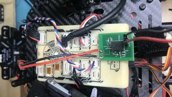
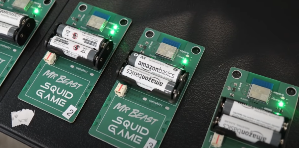
The video documents [William]’s journey, getting 500 copies of a board built and delivered on deadline. As such, there isn’t a ton of detail about the internal workings of the system. A pair of AA batteries feed into a boost converter, which powers an ESP8266 inside an ESP-WROOM-02 module. The ESP drives a few LEDs and a MOSFET. The MOSFET is connected to the star of the show – an MGJ firewire initiator – think of it as a model rocket igniter on steroids.  The initiator hides behind a bag of YouTube-friendly yellow “blood”. When the system is commanded to kill, the initiator pops the bag, spraying blood everywhere.

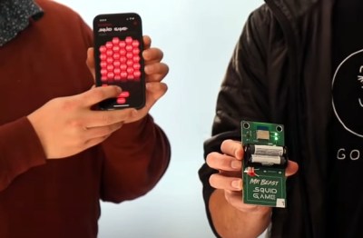
Doing this for one device isn’t so bad, but we’re following Squid Game rules – which means 456 competitors. Further, there were 100 iPhones loaded with a custom kill app for the workers. Add a central server into the mix, and you’ve got 557 devices in close quarters basting on 2.4 GHz and 5.8 GHz. Did we mention that [William] had never done a test with more than a handful of devices?

Want to find out what happens? Check out the video below!

Continue reading “Engineering On A Deadline For Squid Game

NASA Hardware Techniques: Soldering Space Electronics Like It’s 1958

[PeriscopeFilms] on YouTube has many old TV adverts and US government reels archived on their channel, with some really interesting subjects to dive in to. This first one we’re highlighting here is a 1958 film about NASA Soldering Techniques (Video, embedded below), which has some fascinating details about how things were done during the Space Race, and presumably, continue to be done. The overall message about cleanliness couldn’t really be any clearer if they tried — it’s so critical it looks like those chaps in the film spend far more time brushing and cleaning than actually wielding those super clean soldering irons.

Of particular note are some of the details of wire stripping and jointing with components, such as the use of a hot-wire device to remove the insulation from wire, rather than use the kind of stripper we have lying around that cuts into the insulation and slightly distorts the wire in the process. That just won’t do. If they did have to use a cutting-type stripper, it must be precisely the right size for job, and calibrated daily.

The road to the Moon is paved with calibrated wire strippers.

When soldering a pre-tinned wire to a leaded component, a clamp is required to prevent movement of the wire, as is a thermal shunt on the component lead to protect the delicate component from excess heat. They even specify how much to wrap a wire around a terminal to be soldered, never bending the wire more than 180 degrees.

The bottom line in all this is, is that the work must be as perfect as is possible, as there is very little chance of sending someone up to fix a dodgy soldering job, once the assembly is hurtling around the planet. They call it too much of a science to be called an art and too much art to be called a science, and we can sure appreciate that.

As you would expect (and it’s not exactly a big secret) NASA has some very exacting standards for assembly of all hardware, like this great workmanship standard, which is well worth studying. Soldering is an important subject for many of us, we’ve covered the subject of solder metallurgy, as well as looking at how ancient hardware hackers soldered without the benefit of much modern knowledge.

Continue reading “NASA Hardware Techniques: Soldering Space Electronics Like It’s 1958”