At this point, you’ve almost certainly heard about the Atomic Pi. The diminutive board that once served as the guts of a failed robot now lives on as a powerful x86 SBC available at a fire sale price. How long you’ll be able to buy them and what happens when the initial stock runs out is another story entirely, but there’s no denying that folks are already out there doing interesting things with them.
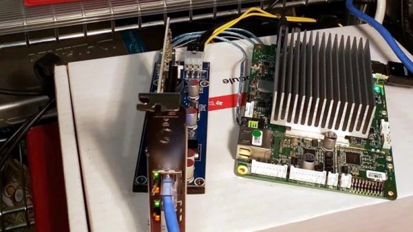
One of them is [Jason Gin], who recently completed an epic quest to add a PCI Express (PCI-E) slot to his Atomic Pi. Things didn’t exactly go according to plan and the story arguably has more lows than highs, but in the end he emerged victorious. He doesn’t necessarily recommend you try the same modification on your own Atomic Pi, but he does think this sets the stage for the development of a more refined upgrade down the line.
 [Jason] explains that the board’s Ethernet controller was already communicating with the Intel Atom x5-Z8350 SoC over PCI-E, so there was never a question about whether or not the modification was possible. In theory, all you needed to do was disable the Ethernet controller and tack on an external PCI-E socket so you could plug in whatever you want. The trick is pulling off the extremely fine-pitch soldering such a modification required, especially considering how picky the PCI Express standard is.
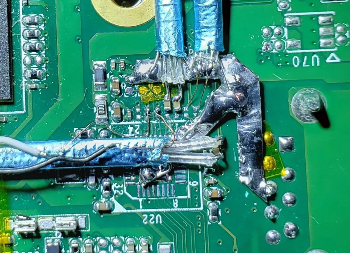
In practice, it took several attempts with different types of wire before [Jason] was able to get the Atomic Pi to actually recognize something plugged into it. Along the way, he managed to destroy the Ethernet controller somehow, but that wasn’t such a great loss as he planned on disabling it anyway. The final winning combination was 40 gauge magnet wire going between the PCB and a thin SATA cable that is mechanically secured to the board with a piece of metal to keep anything from flexing.
At this point, [Jason] has tested enough external devices connected to his hacked-on port to know the modification has promise. But the way he’s gone about it is obviously a bit temperamental, and far too difficult for most people to accomplish on their own anyway. He’s thinking the way forward might be with a custom PCB that could be aligned over the Ethernet controller and soldered into place, though admits such a project is currently above his comfort level. Any readers interested in a collaboration?
Like most of you, we had high hopes for the Atomic Pi when we first heard about it. But since it became clear the board is the product of another company’s liquidation, there’s been some understandable trepidation in the community. Nobody knows for sure what the future looks like for the Atomic Pi, but that’s clearly not stopping hackers from diving in.