Slipcasting Resin Prototypes

[Eric Strebel] doesn’t need an introduction anymore. If there is a picture of an elegantly designed part with a professional finish on our pages, there is a good chance he has a hand in it. This time he is sharing his method of making a part which looks like it is blow-molded but it is not. Blow-molded parts have a distinctive look, especially made with a transparent material and [Eric’s] method certainly passes for it. This could upgrade your prototyping game if you need a few custom parts that look like solidified soap bubbles.

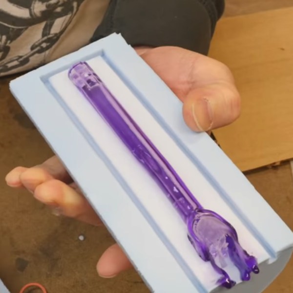
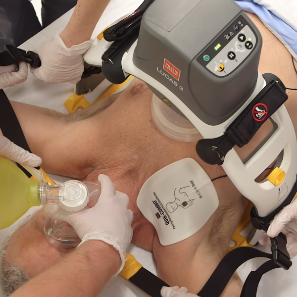
Mold making is not covered in this video, which can also be seen below the break, but we can help you out with a tip or two. For demonstration’s sake, we see the creation of a medical part which has some irregular surfaces. Resin is mixed and degassed then rolled around inside the mold. Then, the big reveal, resin is allowed to drain from the mold. Repeat to achieve the desired thickness.

This is a technique adapted from ceramics called slipcasting. For the curious, an elegant ceramic slipcasting video demonstration can be seen below as well. For an added finishing touch, watch how a laquer logo is applied to the finished part; a touch that will move the look of your build beyond that of a slapdash prototype.

More education from this prolific maker can be seen in his video on painting with a professional-looking finish and his tips for working with foam-core.

Continue reading “Slipcasting Resin Prototypes”

One-key Keyboard Is Exercise In Sub-millimeter Design

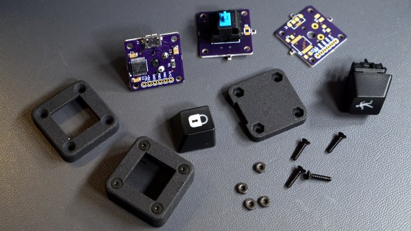
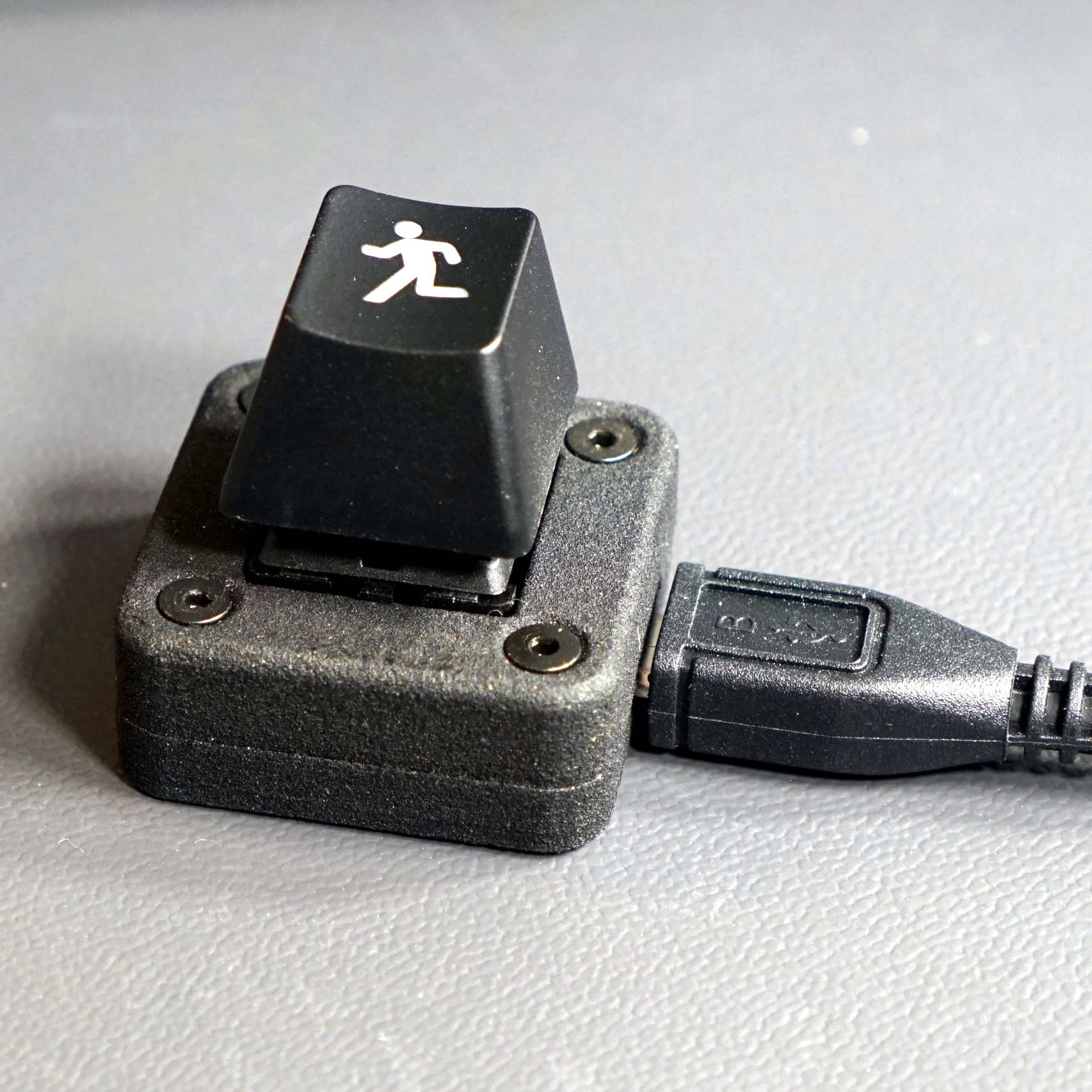
As [Glen] describes it, the only real goal in his decision to design his single-key USB keyboard was to see how small he could build a functional keyboard using a Cherry MX key switch, and every fraction of a millimeter counted. Making a one-key USB keyboard is one thing, but making it from scratch complete with form-fitting enclosure that’s easy to assemble required careful design, and luckily for all of us, [Glen] has documented it wonderfully. (Incidentally, Cherry MX switches come in a variety of qualities and features, the different models being identified by their color. [Glen] is using a Cherry MX Blue, common in keyboards due to its tactile bump and audible click.)

[Glen] steps though the design challenges of making a device where seemingly every detail counts, and explains problems and solutions from beginning to end. A PIC16F1459, a USB micro-B connector, and three capacitors are all that’s needed to implement USB 2.0, but a few other components including LED were added to help things along. The enclosure took some extra care, because not only is it necessary to fit the board and the mounted components, but other design considerations needed to be addressed such as the depth and angle of the countersink for the screws, seating depth and clearance around the USB connector, and taking into account the height of the overmold on the USB cable itself so that the small device actually rests on the enclosure, and not on any part of the cable’s molding. To top it off, it was also necessary to adhere to the some design rules for minimum feature size and wall thicknesses for the enclosure itself, which was SLS 3D printed in nylon.

PCB, enclosure, software, and bill of materials (for single and triple-key versions of the keyboard) are all documented and available in the project’s GitHub repository. [Glen] also highlights the possibility of using a light pipe to redirect the embedded LED to somewhere else on the enclosure; which recalls his earlier work in using 3D printing to make custom LED bar graphs.

3D Printering: When An STL File Is Not Quite Right

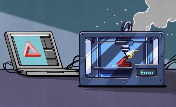
STL files are everywhere. When there’s something to 3D print, it’s probably going to be an STL. Which, as long as the model is good just as it is, is no trouble at all. But sooner or later there will be a model that isn’t quite right in some way and suddenly project progress hits a snag.

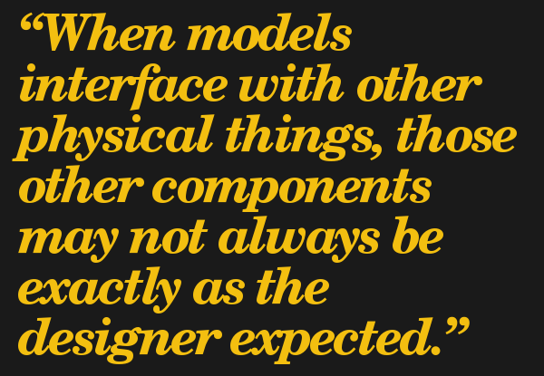
When models interface with other physical things, those other components may not always be exactly as the designer expected. Being mindful about such potential inconsistencies during the design phase can help prevent problems, but it’s not always avoidable. The reason it’s a problem is because an STL file represents a solid model as a finished unit; it is not really intended to be rolled back into CAD programs for additional design changes.

STL files can be edited, but just like re-modeling a component from scratch, it can be a tricky process for those who don’t live and breathe this stuff. I’ll describe a few common issues related to STLs that can hold up getting that new project together, along with ways to deal with them. Thanks to 3D printing becoming much more commonplace, basic tools are within reach of even the least CAD-aware among us.

Continue reading “3D Printering: When An STL File Is Not Quite Right”

ESP Cookbook Goes Beyond Chips And DIPs

Are you putting ESP8266s in all your projects these days, whether they need one or not? We don’t blame you. These boards are cheap, tiny, oh and they have WiFi.

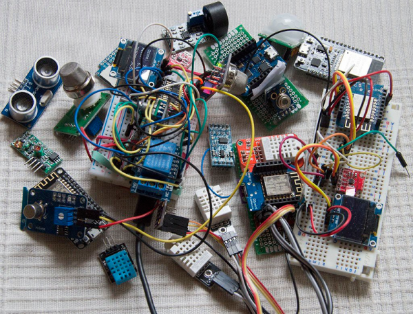
If you want to spend less time writing code and more time blinking RGB LEDs over Wi-Fi, then check out this ESP cookbook over on IO. [Turo Heikkinen] and team are writing a soup-to-nuts guide to these darlings of IoT. The cookbook leads off with pinouts and networking (of course) before moving into more intricate recipes involving popular sensors and displays.

This cookbook is funny, it’s helpful, and it’s really well-organized. We love that they used the details section to create a linked table of contents. The links all drive to a specific Instructions page where each group of code snippets and explanations can be found. It’s still a work in progress, so you might want to follow it for updates. We have a feeling they’re going to expand the dessert section next.

Love the ESP8266, but hate programming them in that wonky form factor? Here’s a handy programming jig you can build.

Pimp My Scope

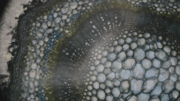
Most of us have heard some form of the adage, “You can buy cheaper, but you’ll never pay less.” It means that cheaper products ultimately do not stand up to the needs of their superior counterparts. Hackers love to prove this aphorism wrong by applying inexpensive upgrades to inexpensive tools to fill up a feature-rich tool bag. Take [The Thought Emporium] who has upgraded an entry-level microscope into one capable of polarized and dark-field microscopy. You can also see the video after the break.

Functionally, polarized images can reveal hidden features of things like striations in crystals or stress lines in hot glue threads. Dark-field microscopy is like replacing the normally glaring white background with a black background, and we here at Hackaday approve of that décor choice. Polarizing filters sheets are not expensive and installation can be quick, depending on your scope. Adding a dark-field filter could cost as much as a dime.

Like most mods, the greatest investment will be your time. That investment will pay back immediately by familiarizing you with your tools and their workings. In the long-run, you will have a tool with greater power.

Simple mods like the light source can be valuable, but upgrades are not limited to optical scopes, an electron microscope was brought back to life with Arduino

Continue reading “Pimp My Scope”

Impossibly Huge Depth Of Focus In Microscope Photographs

Sometimes, less is more. Sometimes, more is more. There is a type of person who believes that if enough photos of the same subject are taken, one of them will shine above the rest as a gleaming example of what is possible with a phone camera and a steady hand. Other people know how to frame a picture before hitting the shutter button. In some cases, the best method may be snapping a handful of photos to get one good one, not by chance, but by design.

[The Thought Emporium]’s video, also below the break, is about getting crisp pictures from a DSLR camera and a microscope using focus stacking, sometimes called image stacking. The premise is to take a series of photos that each have a different part of the subject in focus. In a microscope, this range will be microscopic but in a park, that could be several meters. When the images are combined, he uses Adobe products, the areas in focus are saved while the out-of-focus areas are discarded and the result is a single photo with an impossible depth of focus. We can’t help but remember those light-field cameras which didn’t rely on moving lenses to focus but took many photos, each at a different focal range.

[The Thought Emporium] has shown us his photography passion before, as well as his affinity for taking the cells out of plants and unusual cuts from the butcher and even taking a noble stab at beating lactose intolerance.

Continue reading “Impossibly Huge Depth Of Focus In Microscope Photographs”

Biasing That Transistor: The Common Base Amplifier

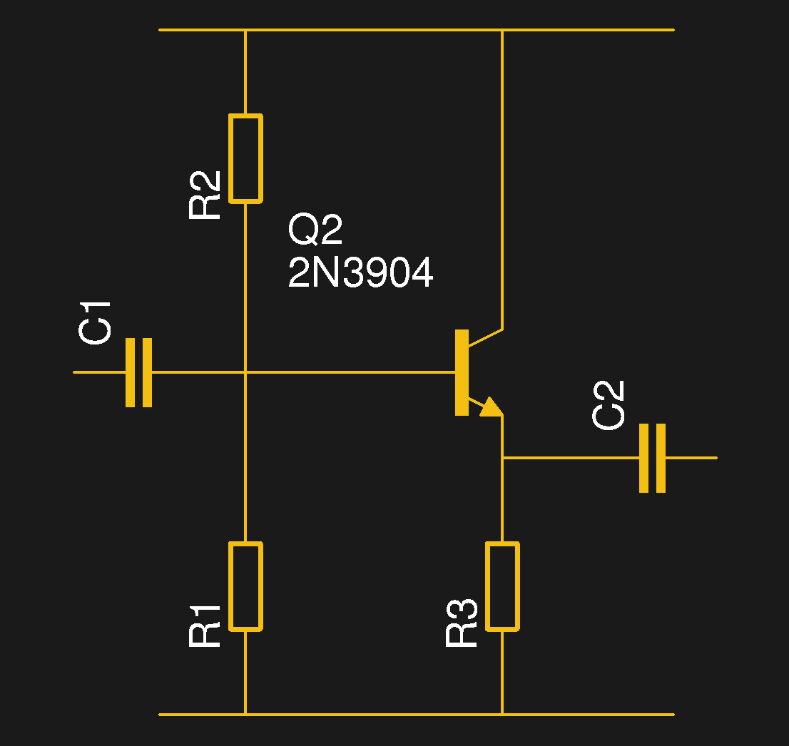
We’ve previously remarked upon a generation lucky enough to be well-versed in microcontrollers and computersised electronics through being brought up on the Arduino or the Raspberry Pi but unlucky enough to have missed out on basic electronics such as how to bias a transistor, and to address that gap we’ve taken a look at the basics of transistor biasing.

All the circuits we worked with in the previous article had the transistor’s emitter taken to ground, took their input from the base, and their output from the collector. This configuration, called a Common Emitter amplifier is probably the most common, but it is far from the only way to use a transistor. Once you have set up the bias voltage as we described to the point at which the transistor is in its linear region, there are several other ways in which the device can be used as an amplifier. The subject of this article is one of these configurations, so described because it takes the transistor’s base to the ground instead of the emitter, as a Common Base amplifier. Continue reading “Biasing That Transistor: The Common Base Amplifier”