We see a lot of clocks here on Hackaday. Some make it easy to tell the time, others are more cryptic. [dragonator] has done something that is so simple, we are surprised it isn’t more common. In a typical mechanical hand clock the minute and hour hands rotate around the same axis. [dragonator] decided to take the minute hand and move it out to the tip of the hour hand.
It works because of a gear system hidden behind the thick hour hand. As the hour hand turns, the gear system rotates, the last gear of which is connected to the minute hand. Since the minute hand rotates 12 times for every one revolution of the hour hand, the gear ratio can easily be calculated.
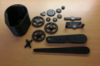 The 3D printed parts were designed by [dragonator] himself. All of the design files are available here for anyone who wants to build one of these neat clocks.
The clock uses a Trinket microcontroller board to keep track of the time and to send step signals to a StepStick that drives a NEMA 17 stepper motor. There is no on-board battery power for this clock, 9-12vdc comes in via a wall wart and is stepped down to 5v by the micro controller’s regulator. Even still, this is a great project that makes it fun to watch time pass, check the video out after the break.