As a writer it’s a pleasure to see one’s work appear from time to time on a physical medium. While newspapers may be shuffling slowly off this mortal coil, there are still a few opportunities to write for printed media. It’s safe to say that no Hackaday scribe has ever managed to have their work published on the medium in this hack though, because it’s a typewriter designed to type on toast.
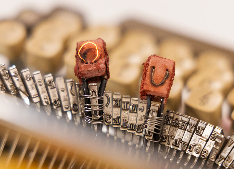 The toaster-typewriter is the work of [Ritika Kedia], and it forms part of her thesis in product design at the Parsons School of Design, New York. It’s written up very much from an artistic rather than a tech perspective, but it’s no less ingenious for that in the way it uses letters formed from hot wire on a clay substrate, mounted on the end of the typewriter arms in front of a toaster.
We’re slightly sad to see that it only has three operable letters at the moment as it’s an artwork rather than a document machine, but we love the idea and wish she had time to develop it further with a full alphabet. You can see a short demo in the video below the break.