According to [Lee Teschler], the classic representation of encoders showing code rings is out of date. His post says that most industrial absolute encoders use a special magnetic sensor known as a Wiegand wire to control costs. To demonstrate he does a teardown of an encoder made by Nidec Avtron Automation, and if you’ve ever wondered what’s inside something like this, you enjoy the post.
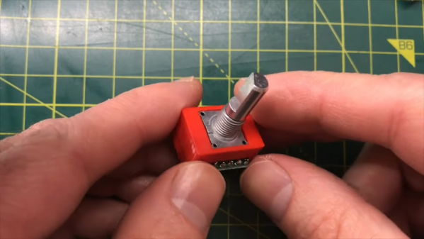
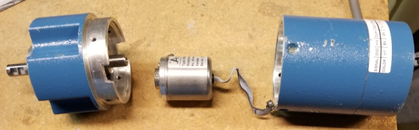
This is a large industrial unit and when you open it up, you’ll get a surprise. Most of the inside is empty! There is a very small encoder inside. The main body protects the inside and holds the large bearings. The real encoder looks more like a toy car motor than anything else.
The inner can is nearly empty, too. But it does have the part we are interested in. There’s a Melexis Hall effect sensor The Weigand wire is a special magnetic wire with an outer sheath that is resistant to having its magnetic field reversed and an inner core that isn’t. Until an applied magnetic field reaches a certain strength, the wire will stay magnetized in one direction. When the field crosses the threshold, the entire wire changes magnetic polarity rapidly. The effect is independent of the rate of change of the applied magnetic field.
In other words, like old core memory, the wire has strong magnetic hysteresis. Between pulses from the Weigand wire and information from the Hall effect sensor, you can accurately determine the position of the shaft.
It is always amazing to us how many modern pieces of gear are now mostly empty with the size of the device being driven by physical constraints and not the electronics within.