Assess Your Output With A Cheap DIY Urine Flowmeter

Some things about the human body are trivial to measure. Height, weight, blood pressure, pulse, temperature — these are all easily quantifiable with the simplest of instruments and can provide valuable insights into our state of health. Electrical activity in the heart and the brain can be captured with more complex instruments, too, and all manner of scopes can be inserted into various orifices to obtain actionable information about what’s going on.

But what about, err, going? Urine flow can be an important leading indicator for a host of diseases and conditions, but it generally relies on subjective reports from the patient. Is there a way to objectively measure how well urine is flowing? Of course there is.

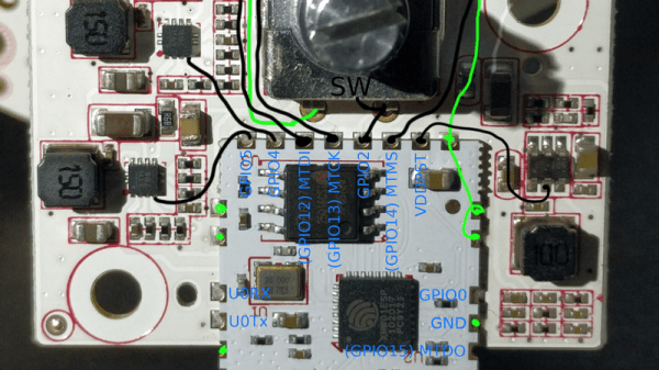
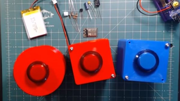
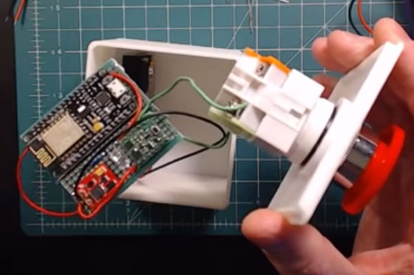
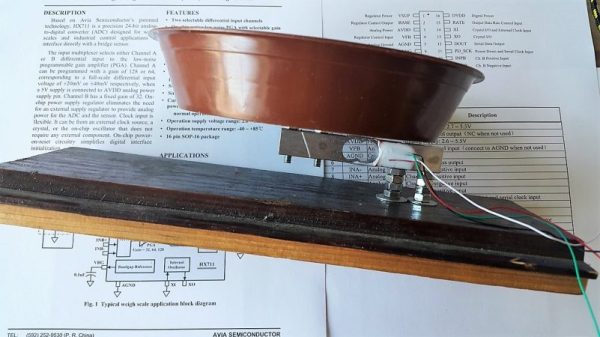
The goal for [GreenEyedExplorer]’s simple uroflowmeter is simple: provide a cheap, easy to use instrument that any patient can use to quantify the rate of urine flow while voiding. Now, we know what you’re thinking — isn’t liquid flow usually measured in a closed system with a paddlewheel or something extending into the stream? Wouldn’t such a device for urine flow either be invasive or messy, or both? Rest assured, this technique is simple and tidy. A small load cell is attached to an ESP8266 through an HX711 load cell amp. A small pan on the load cell receives urine while voiding, and the force of the urine striking the pan is assessed by the software. Reports can be printed to share with your doctor, and records are kept to see how flow changes over time.

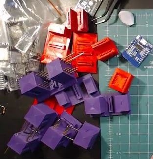
All kidding aside, this could be an important diagnostic tool, and at 10€ to build, it empowers anyone to take charge of their health. And since [GreenEyedExplorer] is actually a urologist, we’re taking this one seriously.

Continue reading “Assess Your Output With A Cheap DIY Urine Flowmeter”

Simple Decoder Serves As Solo Ham’s Test Buddy

For a hobby that’s ostensibly all about reaching out to touch someone, ham radio can often be a lonely activity. Lots of hams build and experiment with radio gear much more than they’re actually on the air, improving their equipment iteratively. The build-test-tweak-repeat cycle can get a little tedious, though, especially when you’re trying to assess signal strength and range and can’t find anyone to give you a report.

To close the loop on field testing, [WhiskeyTangoHotel] threw together a simple ham radio field confirmation unit that’s pretty slick. It relies on the fact that almost every ham radio designed for field use incorporates a DTMF encoder in the microphone or in the transceiver itself. Hams have used Touch Tones for in-band signaling control of their repeaters for decades, and even as newer digital control methods have been introduced, good old analog DTMF hangs in there. The device consists of a DTMF decoder attached to the headphone jack of a cheap handy talkie. When a DTMF tone is received, a NodeMCU connected to the decoder calls an IFTTT job to echo the key to [WTH]’s phone as an SMS message. That makes it easy to drive around and test whether his mobile rig is getting out. And since the receiver side is so portable, there’s a lot of flexibility in how tests can be arranged.

On the fence about ham as a hobby? We don’t blame you. But fun projects like this are the perfect excuse to go get licensed and start experimenting.

Continue reading “Simple Decoder Serves As Solo Ham’s Test Buddy”

Dumb Down Your Xiaomi Smart Lamp With A Custom Firmware

Undoubtedly, the ESP8266’s biggest selling point is its WiFi capability for a ridiculously low price. Paranoid folks probably await the day its closed-source firmware bits will turn against humanity in a giant botnet, but until then, hobbyists and commercial vendors alike will proceed putting them in their IoT projects and devices. One of those devices is the Yeelight desk lamp that lets you set its color temperature and brightness via mobile app.

[fvollmer] acquired such a lamp, and while he appreciated its design and general concept, he wasn’t happy that it communicates with external servers. So he did the only reasonable thing and wrote his own firmware that resembles the original functionality, but leaves out the WiFi part. After all, the ESP8266 has still a lot to offer in its core essence: a full-blown 32-bit microcontroller with support for the most common, hobbyist-friendly SDKs.

The lamp’s color temperature and brightness are set with a rotary encoder / push button combo switch, and the LEDs themselves are controlled via PWM. All things considered, it’s a rather straightforward endeavour, for which [fvollmer] chose the standalone C SDK. And in the end, it’s not like he’s unreasonably cautious to keep some control over his household items.

Evolution Of The ESP8266 Party Button

Sometimes the best part of building something is getting to rebuild it again a little farther down the line. Don’t tell anyone, but sometimes when we start a project we don’t even know where the end is going to be. It’s a starting point, not an end destination. Who wants to do something once when you could do it twice? Maybe even three times for good measure?

Original version of the Party Button

That’s what happened when [Ryan] decided to build a wireless “party button” for his kids. Tied into his Home Assistant automation system, a smack of the button plays music throughout the house and starts changing the colors on his Philips Hue lights. His initial version worked well enough, but in the video after the break, he walks through the evolution of this one-off gadget into a general purpose IoT interface he can use for other projects.

The general idea is pretty simple, the big physical button on the top of the device resets the internal ESP8266, which is programmed to connect to his home WiFi and send a signal to his MQTT server. In the earlier versions of the button there was quite a bit of support electronics to handle converting the momentary action of the button to a “hard” power control for the ESP8266. But as the design progressed, [Ryan] realized he could put the ESP8266 to deep sleep after it sends the signal, and just use the switch to trigger a reset on the chip.

Additional improvements in the newer version of the button include switching from alkaline AA batteries to a rechargeable lithium-ion pack, and even switching over to a bare ESP8266 rather than the NodeMCU development board he was using for the first iteration.

For another take on MQTT home automation with the ESP8266, check out this automatic garage door control system. If the idea of triggering a party at the push of a button has your imagination going, we’ve seen some elaborate versions of that idea as well.

Continue reading “Evolution Of The ESP8266 Party Button”

3D Printed ESP8266 Programming Jig

The various development boards such as the NodeMCU or Wemos D1 make working with the ESP8266 an absolute breeze. If they have a downside, it is that they are larger than the bare ESP2866, and of course cost a bit more. Just as with the Arduino, once you have the wiring sorted out and the code more or less finalized, your best bet is to ditch the unnecessary support hardware and use the bare module to save space and money in your final design.

The design took a few revisions to get right

Unfortunately, the ESP8266 form factor isn’t terribly forgiving when it comes time for hooking up a programmer. Rather than having to solder a serial adapter to the chip to flash it, [Ryan] came up with a slick 3D printed programming jig that uses pogo pins. If you have to program these boards in bulk, a jig like this can save a massive amount of time and aggravation.

Beyond the 3D printed holder for the pogo pins, this programmer uses a FTDI USB-to-serial adapter, a couple passive components to smooth out the power going into the chip, and a couple buttons.

In the video after the break, [Ryan] walks through the many iterations it took to get the 3D printed aspect of the jig worked out. The design went through a few rather large revisions, including one that fundamentally changed the whole form factor. Even with the jig now working, he mentions that he might circle back around and try it from a different angle.

Programming jigs are a staple of electronics manufacturing, and we’ve covered quite a few that have helped transformed a proof of concept into a small scale production runs.

Continue reading “3D Printed ESP8266 Programming Jig”

Control A Swarm Of RC Vehicles With ESP8266

Over at RCgroups, user [Cesco] has shared a very interesting project which uses the ever-popular ESP8266 as both a transmitter and receiver for RC vehicles. Interestingly, this code makes use of the ESP-Now protocol, which allows devices to create a mesh network without the overhead of full-blown WiFi. According to the Espressif documentation, this mode is akin to the low-power 2.4GHz communication used in wireless mice and keyboards, and is designed specifically for persistent, peer-to-peer connectivity.

Switching an ESP8266 between being a transmitter or receiver is as easy as commenting out a line in the source code and reflashing the firmware. One transmitter (referred to as the server in the source code) can command eight receiving ESP8266s simultaneously. [Cesco] specifically uses the example of long-range aircraft flying in formation; only coming out of the mesh network when it’s time to manually land each one.

[Cesco] has done experiments using both land and air vehicles. He shows off a very hefty looking tracked rover, as well as a quickly knocked together quadcopter. He warns the quadcopter flies like “a wet sponge”, but it does indeed fly with the ESP’s handling all the over the air communication.

To be clear, you still need a traditional PPM-compatible RC receiver and transmitter pair to use his code. The ESPs are simply handling the over-the-air communication. They aren’t directly responsible for taking user input or running the speed controls, for example.

This isn’t the first time we’ve seen an ESP8266 take the co-pilot’s seat in a quadcopter, but the maniacal excitement we feel when considering the possibility of having our very own swarm of flying robots gives this particular project an interesting twist.

Massive Shift Register Switches Lights

Sometimes you have to switch a light. Maybe it’s an LED but sometimes it’s mains-powered. That’s not too hard, a transistor and a relay should do it. If you have to switch more lights, that’s not too bad either, as long as your microcontroller has enough free GPIOs. But, if you need to switch a large number of lights, like 256 of them, for example, you’re going to need something else.

[Jan]’s project didn’t switch quite that many lights, but 157 of them is still enough of a chore to need a creative solution so he decided to use a 256-bit shift register to do the legwork. The whole thing is powered by a NodeMCU ESP8266 and was professionally built on DIN rails in a metal enclosure.

The build is interesting, both from a technical point of view and from an artistic one. It looks like it uses more than a mile of wiring, too. The source code is also available on the project page if you happen to have a need for switching a huge number of lightbulbs. Incandescent blulbs aren’t only good for art installations and lamps, though, they can also be used in interesting oscillator circuits too.