Harmonic Analyzer Does It With Cranks And Gears

Before graphic calculators and microcomputers, plotting functions were generally achieved by hand. However, there were mechanical graphing tools, too. With the help of a laser cutter, it’s even possible to make your own!

The build in question is nicknamed the Harmonic Analyzer. It can be used to draw functions created by adding sine waves, a la the Fourier series. While a true Fourier series is the sum of an infinite number of sine waves, this mechanical contraption settles on just 5.

This is achieved through the use of a crank driving a series of gears. The x-axis gearing pans the notepad from left to right. The function gearing has a series of gears for each of the 5 sinewaves, which work with levers to set the magnitude of the coefficients for each component of the function. These levers are then hooked up to a spring system, which adds the outputs of each sine wave together. This spring adder then controls the y-axis motion of the pen, which draws the function on paper.

It’s a great example of the capabilities of mechanical computing, even if it’s unlikely to ever run Quake. Other DIY mechanical computers we’ve seen include the Digi-Comp I and a wildly complex Differential Analyzer. Video after the break.

Continue reading “Harmonic Analyzer Does It With Cranks And Gears”

Robot Joints Go Modular With This Actuator Project

[John Lauer] has been hard at work re-thinking robot arms. His project to create modular, open source actuators that can be connected to one another to form an arm is inspiring, and boasts an impressively low parts cost as well. The actuators are each self-contained, with an ESP32 and a design that takes advantage of the form factors of inexpensive modules and parts from vendors like Aliexpress.

Flex spline in action, for reducing backlash

Each module has 3D printed gears (with an anti-backlash flex spline), an RGB LED for feedback, integrated homing, active cooling, a slip ring made from copper tape, and a touch sensor dial on the back for jogging and training input. The result is a low backlash, low cost actuator that keeps external wiring to an absolute minimum.

Originally inspired by a design named WE-R2.4, [John] has added his own twist in numerous ways, which are best summarized in the video embedded below. That video is number three in a series, and covers the most interesting developments and design changes while giving an excellent overview of the parts and operation (the video for part one is a basic overview and part two shows the prototyping process, during which [John] 3D printed the structural parts and gears and mills out a custom PCB.)

Continue reading “Robot Joints Go Modular With This Actuator Project”

Bend Some Bars With A Flywheel

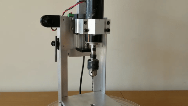
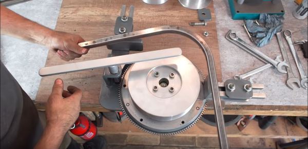
The ability to look at a pile of trash, and see the for treasure is a skill we hold in high regard around here. [Meanwhile in the Garage] apparently has this skill in spades and built himself a metal bar bending machine using an old flywheel and starter pinion gear.

To bend metal using muscle power alone requires some sort of mechanical advantage. Usually this involves a bending tool with a long lever, but [Meanwhile in the Garage] decided to make use of the large gear ratio between a car’s starter motor and the flywheel it drives. This does away with the need for a long lever and allows bending to almost 270° with a larger radius. Lathe and milling work features quite prominently, including to make the bend formers, drive shaft and bushings and to modify the flywheel to include a clamp. The belt sander that is used to finish a number of the parts is also his creation. While the machine tools definitely helped, a large amount of creativity and thinking outside the box made this project possible and worth the watch.

We’ve featured a number of scrap-built tools including a milling machine, sheet metal hole punch and a hydraulic bench vice. Keep them coming!

Steampunk Radio Looks The Business

Radios are, by and large, not powered by steam. One could make the argument that much of our municipal electricity supply does come via steam turbines, but that might be drawing a long bow. Regardless, steampunk remains a popular and attractive aesthetic, and it’s the one that [Christine] selected for her radio build.

The build cribs from [Christine’s] earlier work on a VFD alarm clock, using similar tubes and driver chips to run the display. FM radio and amplification are courtesy of convenient modules. Tubes are fitted for aesthetic purposes, artfully lit with a smattering of color-changing LEDs. Perhaps the neatest touch is the use of valve handles to control tuning and volume. A stepper motor turns a series of gears, as is mandatory for any true steampunk build, and there’s even an electromagnetic actuator to make the Morse key move. To run it all, a pair of Arduino Megas are charged with handling the I/O needs of all the various systems.

It’s a fancy build that shows how far the rabbit hole you can go when chasing a particular look and feel. It’s a radio that would make a great conversation piece on any hacker’s coffee table.  If that’s not enough, consider going for a whole laptop. Video after the break. Continue reading “Steampunk Radio Looks The Business”

Home Made Gears Save This Shredder

It’s very likely that a majority of readers will have had a gear fail in a piece of equipment, causing it to be unrepairable. This is a problem particularly with plastic gears, which shed teeth faster than a child who has discovered the financial returns of the Tooth Fairy.

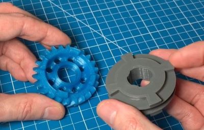
[BcastLar] has a shredder with a gear that has, well, shredded. He’s posted a video series over three parts that while ostensibly about fixing his shredder, is in reality a three-part tutorial on how to create custom gears using FreeCAD. While the principles of a gear are readily apparent to most observers their intricacies hide significant complexity which he does a great job of explaining. How to measure the parameters of a given gear, explaining mysteries such as pitch angle or beta, he breaks everything down in easy to understand steps.

His tool of choice is FreeCAD, and while he explains that FreeCAD has the ability to make gears from scratch the tool employed in the videos is the Gear Workbench plugin. He shows how this software removes the complexity of creating a gear, and shows the process on his screen as he creates the custom shredder part.

Finally, the process of 3D printing the gear is explained. You might ask why not machine it, to which he responds that tooling for non-standard gear profiles is prohibitively expensive. We’ve placed all three videos below the break, and we think you might want to make yourself a cup of tea or something and work through them.

Thanks [Andy Pugh] for the tip.

Continue reading “Home Made Gears Save This Shredder”

A Compact Strain Wave Gear Assembly

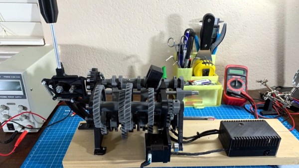
Strain wave gearing is a clever way to produce a high-efficiency, high ratio gearbox within a small space. It involves an outer fixed ring of gear teeth and an inner flexible ring of teeth which are made to mesh with the outer by means of an oval rotor distorting the ring. They aren’t cheap, so [Leo Vu] has had a go at producing some 3D-printable strain wave gearboxes that you could use in your robotic projects.

He’s created his gearbox in three ratios, 1:31, 1:21 and 1:15. It’s not the most miniature of devices at 145mm in diameter and weighing well over a kilogram, but we can still imagine plenty of exciting applications for it. We’d be curious as to how tough a 3D printed gear can be, but we’d expect you’ll be interested in it for modest-sized robots rather than Formula One cars. There’s a video featuring the gearbox which we’ve placed below the break.

This certainly isn’t the first strain wave gearset we’ve brought you, more than one 3D printed project has graced these pages. We’ve even brought you a Lego version. Continue reading “A Compact Strain Wave Gear Assembly”

3D-Printed Mobius Strip Of Gears

Exploring the mathematics behind everyone’s favourite unorientable single-sided surface can be quite the mind-bending exercise, so it’s nice that it’s so easy to make a Mobius strip out of paper and a single piece of tape. That demonstration was far from enough for [elmins]. who printed this Mobius strip of gears. The teeth fit together, and all the gears move, but there is still only one side and one edge (we think).

This animation helped spawn the project.

The idea to tackle the project came from seeing an animation of Mobius gears. Wondering if it would be possible to actually create such a thing, [elmins] got to work. The design is printed in 60 pieces, 30 each for the inner and outer parts. The entire assembly is printed in PETG, an unconventional choice but by no means unsuitable. 285 ball bearings help the rings rotate.

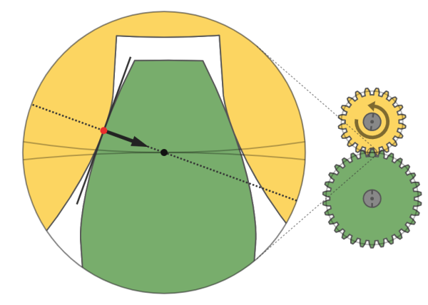
The gears use a standard involute bevel profile, though [elmins] suspects this could be an area of further optimisation. The parts were printed in an orientation to ensure the print lines run around the races, allowing for minimal finishing and smooth rolling of the bearings. This is a good study of just what can be achieved with some smart modelling and perseverance.

If you’re thirsty for more madcap machining, consider exploring the concept of the Reuleaux triangle bearing.