Open Source, DIY Soldering Robot

After [Brian] starting selling his own Raspberry Pi expansion boards, he found himself with a need for a robot that could solder 40-pin headers for him. He first did what most people might do by looking up pre-built solutions. Unfortunately everything he found was either too slow, too big, or cost as much as a new car. That’s when he decided to just build his own soldering robot.

The robot looks similar to many 3D printer designs we’ve seen in the past, with several adjustments. The PCBs get mounted to a flat piece of aluminum dubbed the “PCB caddy”. The PCBs are mounted with custom-made pins that thread into the caddy. Once the PCBs are in place, they are clamped down with another small piece of aluminum. A computer slowly moves the caddy in one direction, moving the header’s pins along the path of the soldering irons one row at a time.

The machine has two soldering irons attached, allowing for two pins to be soldered simultaneously. The irons are retracted as the PCB caddy slides into place. They irons are then lowered onto the pins to apply heat. Two extruders then push the perfect amount of solder onto each pin. The solder melts upon contact with the hot pins, just as it would when soldered by hand.

The system was originally designed to be run on a Windows 8.1 tablet computer, but [Brian] found that the system’s internal battery would not charge while also acting like a USB host. Instead, they are running the Windows WPF application on full PC. All of the software and CAD files can be found on [Brian’s] github page. Also be sure to check out the demo video below. Continue reading “Open Source, DIY Soldering Robot”

Arduino GPS

A Simple And Inexpensive GPS Navigation Device

There are plenty of GPS navigation units on the market today, but it’s always fun to build something yourself. That’s what [middelbeek] did with his $25 GPS device. He managed to find a few good deals on electronics components online, including and Arduino Uno, a GPS module, and a TFT display.

In order to get the map images on the device, [middelbeek] has to go through a manual process. First he has to download a GEOTIFF of the area he wants mapped. A GEOTIFF is a metadata standard that allows georeferencing information to be embedded into a TIFF image file.  [middelbeek] then has to convert the GEOTIFF into an 8-bit BMP image file. The BMP images get stored on an SD card along with a .dat file that describes the boundaries of each BMP. The .dat file was also manually created.

The Arduino loads this data and displays the correct map onto the 320×240 TFT display. [middelbeek] explains on his github page that he is currently unable to display data from two map files at once, which can lead to problems when the position moves to the edge of the map. We suspect that with some more work and tuning this system could be improved and made easier to use, of course for under $25 you can’t expect too much.

Kitchen Timer

A Kitchen Timer Fit For MacGyver

Here’s a project that you don’t want to bring into an airport, ship through the mail, or probably even remove from your home. [ProjectGeek] has built himself a simple kitchen timer masquerading as a bomb. The build is actually pretty simple, but the end result is something that would look at home in a Hollywood action flick.

The timer circuit is built from four simple components. An 8051 microcontroller board is used as the primary controller and timer. The code is available on GitHub. This board is attached to a another board containing four momentary push buttons. These are used to program the timer and to stop the buzzing. Another board containing four 7-segment displays is used to show the remaining time on the timer. A simple piezo buzzer is used to actually alert you when the timer has run out. All of these components are connected with colorful jumper wires.

The physical part of this build is made from easily available components. Old newspapers are rolled up to form the “explosive” sticks. These are then covered in plain brown paper ordinarily used to cover text books. The rolls are bundled together and fixed with electrical tape. The electronics can then be attached to the base with some hot glue or double-sided tape.

Whiteboard Clock

Whiteboard Clock Draws The Time

[Maurice] recently built a clock that draws the time (Google Doc) on a white board. We’ve seen plenty of clock hacks in the past, and even a very similar one. It’s always fun to see the different creative solutions people can come up with to solve the same problem.

This device runs on a PIC16F1454 microcontroller. The code for the project is available on GitHub. The micro is also connected to a 433MHz receiver. This allows a PC to keep track of the time, instead of having to include a real-time clock in the circuit. The USB connector is only used for power. All of the mounting pieces were designed in OpenSCAD and printed on a 3D printer. Two servos control the drawing arms. A third servo can raise and lower the marker to the whiteboard. This also has the added benefit of being able to place the marker tip inside of an eraser head. That way the same two servos can also erase the writing.

The communication protocol for this systems is interesting. The transmitter shows up on [Maurice’s] PC as a modem. All he needs to do to update the time is “echo 12:00 > /dev/whiteboard”. In this case, the command is run by a cron job every 5 minutes. This makes it easy to tweak the rate at which the time updates on the whiteboard. All communication is done one-way. The drawing circuit will verify the checksum each time it receives a message. If the check fails, the circuit simply waits for another message. The computer transmits the message multiple times, just in case there is a problem during transmission.

Strobe Remote

Reverse Engineering A Wireless Studio Lighting Remote

If you want to take a photograph with a professional look, proper lighting is going to be critical. [Richard] has been using a commercial lighting solution in his studio. His Lencarta UltraPro 300 studio strobes provide adequate lighting and also have the ability to have various settings adjusted remotely. A single remote can control different lights setting each to its own parameters. [Richard] likes to automate as much as possible in his studio, so he thought that maybe he would be able to reverse engineer the remote control so he can more easily control his lighting.

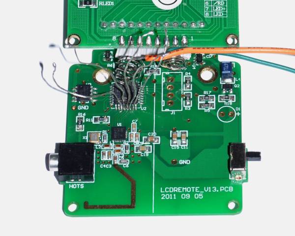
[Richard] started by opening up the remote and taking a look at the radio circuitry. He discovered the circuit uses a nRF24L01+ chip. He had previously picked up a couple of these on eBay, so his first thought was to just promiscuously snoop on the communications over the air. Unfortunately the chips can only listen in on up to six addresses at a time, and with a 40-bit address, this approach may have taken a while.

Not one to give up easily, [Richard] chose a new method of attack. First, he knew that the radio chip communicates to a master microcontroller via SPI. Second, he knew that the radio chip had no built-in memory. Therefore, the microcontroller must save the address in its own memory and then send it to the radio chip via the SPI bus. [Richard] figured if he could snoop on the SPI bus, he could find the address of the remote. With that information, he would be able to build another radio circuit to listen in over the air.

Using an Open Logic Sniffer, [Richard] was able to capture some of the SPI communications. Then, using the datasheet as a reference, he was able to isolate the communications that stored information int the radio chip’s address register. This same technique was used to decipher the radio channel. There was a bit more trial and error involved, as [Richard] later discovered that there were a few other important registers. He also discovered that the remote changed the address when actually transmitting data, so he had to update his receiver code to reflect this.

The receiver was built using another nRF24L01+ chip and an Arduino. Once the address and other registers were configured properly, [Richard’s] custom radio was able to pick up the radio commands being sent from the lighting remote. All [Richard] had to do at this point was press each button and record the communications data which resulted. The Arduino code for the receiver is available on the project page.

[Richard] took it an extra step and wrote his own library to talk to the flashes. He has made his library available on github for anyone who is interested.

Solderless Noise-o-Tron Kit Makes Noise At Chicago Makerfaire

Noise-o-Tron

Anyone who’s manned a hackerspace booth at an event knows how difficult it can be to describe to people what a hackerspace is. No matter what words you use to describe it, nothing really seems to do it justice. You simply can’t use words to make someone feel that sense of accomplishment and fun that you get when you learn something new and build something that actually works.

[Derek] had this same problem and decided to do something about it. He realized that in order to really share the experience of a hackerspace, he would have to bring a piece of the hackerspace to the people.  That meant getting people to build something simple, but fun. [Derek’s] design had to be easy enough for anyone to put together, and inexpensive enough that it can be produced in moderate quantities without breaking the bank.

[Derek] ended up building a simple “optical theremin”. The heart of this simple circuit is an ATTiny45. Arduino libraries have already been ported to this chip, so all [Derek] had to do was write a few simple lines of code and he was up and running. The chip is connected to a photocell so the pitch will vary with the amount of light that reaches the cell. The user can then change the pitch by moving their hand closer or further away, achieving a similar effect to a theremin.

[Derek] designed a simple “pcb” out of acrylic, with laser cut holes for all of the components. If you don’t have access to a laser cutter to cut the acrylic sheets, you could always build your own. The electronic components are placed into the holes and the leads are simply twisted together. This allows even an inexperienced builder to complete the project in just five to ten minutes with no complicated tools. The end result of his hard work was a crowded booth at a lot of happy new makers. All of [Derek’s] plans are available on github, and he hopes his project will find use at Makerfaires and hackerspace events all over the world.

Status Light Tells You The Code Is Borked Again

status light

[Arthur] is teaching himself product development. Rather than create a few mock-up products, he’s taking the path of designing real devices he can use. His current device is a status light for automated software tests.  We’ve seen test and GitHub status lights before, however this is the first one to integrate with an outside web service. The status light’s state is based upon output from CodeShip, an online continuous deployment test engine.

The electronic design is simple. An Electric Imp retrieves test status data from CodeShip. The Imp then sends the status data over two GPIO lines to an AdaFruit Trinket. The Trinket controls a NeoPixel ring. A green ring indicates all tests are passing. Purple means tests are in progress. A spinning red ring (of death) means one or more tests have failed. Power is supplied via a mini USB connector.

[Arthur] spent quite a bit of time on the mechanical design of the status light as well. All the parts are 3D printed. This allowed him to quickly go through several revisions of each part. We like the use of white PLA for a frosted effect on the top section of the light, as it diffuses the eye piercing glow from all those RGB LEDs. As a finishing touch, [Arthur] created a fake product page for his light. He doesn’t have any plans to sell it, but we hope he drops the source and STL files so we can create one of our own.

Continue reading “Status Light Tells You The Code Is Borked Again”