Say you have a guitar, an expensive guitar – one of only three like it. And say this guitar sounds great, but it’s missing something. It needs something, but something that won’t ruin the finish. Over at Sparkfun, [Englandsaurus] was asked to come up with a really cool looking mod to a three-of-a-kind guitar – covering the body with LED strips to create light patterns on the guitar.
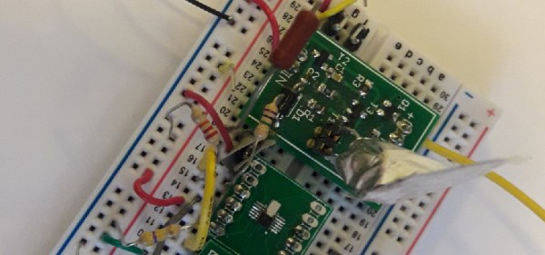
In order not to damage or modify the guitar [Englandsaurus] sandwiched the body between two plexiglass sheets, connected together by 3D printed clips. The clips have a dual purpose – they hold the plexiglass pieces to the guitar and also act as conduits for a pair of fiber optic tubes that run around the edge of the body. In order that the color goes all the way around the guitar’s edge without a break in the light, the fiber optic cables are offset. At each clip light is fed into them. One cable runs between two clips, skipping one in between, and the second cable runs between the skipped clips. This allows light to flow around the guitar’s body.
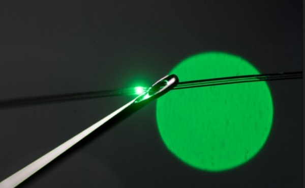
At nearly 500W at full-white, these LEDs draw a lot of power, however, at full brightness they’re overpoweringly bright, so [Englandsaurus] used some WonderFlex, a moldable, diffuse plastic sheet, to cover them. Even with this, the LEDs aren’t run at full brightness. The fiber optic cables, though, need full brightness due to their covering.
Around 1600 LEDs went in to this mod and the guitar itself hasn’t been modified. Everything is removable, and the guitar would go back to its original self if the strips were taken off. Take a look at Strumbot, another project where the original guitar wasn’t modified, or a really cool scrap metal guitar.