When you think of a bicycle and an Eddy, you’d be forgiven for thinking first of Eddy Merckx, one of the most successful competitive cyclists to ever live. But this bicycle, modified by [Tom Stanton] as shown in the video below the break, has been modified by ditching its direct drive gearing in favor of using the friction-like eddy currents between magnets and copper to transfer power to the wheel.
Before even beginning to construct a mechanism for powering the bicycle, [Tom] had to figure out the basics: what kind of materials could be used for a metal disk? The answer, after much testing, turned out to be copper. What kind of magnets work best, and in what formation? Expensive high grade, aligned North to South pole for added eddy-dragging goodness. Would the mechanism work with any efficiency?
The end result is interesting to watch, and it’s not exactly as you’d have expected. Yes, eddy currents drive the copper hub, but at a 100 RPM difference. Where does all of that energy go? Hint: not to the wheel, and certainly not into propelling the bicycle. All in all it’s a fantastic experiment with unpredictable results.
If bicycle based bumbling about bakes your biscuits, you might appreciate this tennis-ball-enhanced ride too.
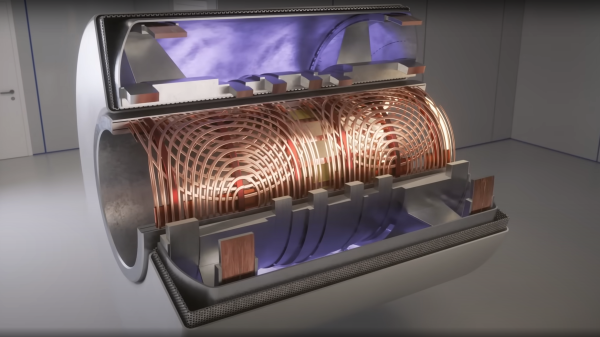
Of all the high-tech medical gadgets we read about often, the Magnetic Resonance Imaging (MRI) machine is possibly the most mysterious of all. The ability to peer inside a living body, in a minimally invasive manner whilst differentiating tissue types, in near real-time was the stuff of science fiction not too many years ago. Now it’s commonplace. But how does the machine actually work? Real Engineering on YouTube presents the Insane Engineering of MRI Machines to help us along this learning curve, at least in a little way.
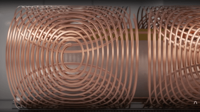
Both types of gradient coil are stacked around the subject inside the main field coil
The basic principle of operation is to align the spin ‘axis’ of all the subject’s hydrogen nuclei using an enormous magnetic field produced by a liquid-helium-cooled superconducting electromagnet. The spins are then perturbed with a carefully tuned radio frequency pulse delivered via a large drive coil.
After a short time, the spins revert back to align with the magnetic field, remitting a radio pulse at the same frequency. Every single hydrogen nucleus (just a proton!) responds at roughly the same time, with the combined signal being detected by the receive coil (often the same physical coil as the driver.)
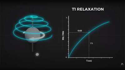
Time taken for the perturbed spin to return to magnetic alignment
There are two main issues to solve. Obviously, the whole body section is ‘transmitting’ this radio signal all in one big pulse, so how do you identify the different areas of 3D space (i.e. the different body structures) and how do you differentiate (referred to as contrast) different tissue types, such as determine if something is bone or fat?
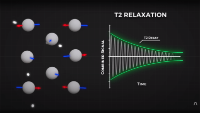
By looking at the decay envelope of the return pulse, two separate measures with different periods can be determined; T1, the spin relaxation period, and T2, the total spin relaxation period. The first one is a measure of how long it takes the spin to realign, and the second measures the total period needed for all the individual interactions between different atoms in the subject to settle down. The values of T1 and T2 are programmed into the machine to adjust the pulse rate and observation time to favor the detection of one or the other effect, effectively selecting the type of tissue to be resolved.
Time taken for the relative phasing inside a tissue locality to settle down to the same average spin alignment
The second issue is more complex. Spatial resolution is achieved by first selecting a plane to virtually slice the body into a 2D image. Because the frequency of the RF pulse needed to knock the proton spin out of alignment is dependent upon the magnetic field strength, overlaying a second magnetic field via a gradient coil allows the local magnetic field to be tuned along the axis of the machine and with a corresponding tweak to the RF frequency an entire body slice can be selected.
All RF emissions from the subject emanate from just the selected slice reducing the 3D resolution problem to a 2D problem. Finally, a similar trick is applied orthogonally, with another set of gradient coils that adjust the relative phase of the spins of stripes of atoms through the slice. This enables the use of a 2D inverse Fourier transform of multiple phase and frequency combinations to image the slice from every angle, and a 2D image of the subject can then be reconstructed and sent to the display computer for the operator to observe.
Neuroscientists have been mapping and recreating the nervous systems and brains of various animals since the microscope was invented, and have even been able to map out entire brain structures thanks to other imaging techniques with perhaps the most famous example being the 302-neuron brain of a roundworm. Studies like these advanced neuroscience considerably but even better imaging technology is needed to study more advanced neural structures like those found in a mouse or human, and this advanced MRI machine may be just the thing to help gain better understandings of these structures.
A research team led by Duke University developed this new MRI technology using an incredibly powerful 9.4 Tesla magnet and specialized gradient coils, leading to an image resolution an impressive six orders of magnitude higher than a typical MRI. The voxels in the image measure at only 5 microns compared to the millimeter-level resolution available on modern MRI machines, which can reveal microscopic details within brain tissues that were previously unattainable. This breakthrough in MRI resolution has the potential to significantly advance understanding of the neural networks found in humans by first studying neural structures in mice at this unprecedented detail.
The researchers are hopeful that this higher-powered MRI microscope will lead to new insights and translate directly into advancements healthcare, and presuming that it can be replicated, used on humans safely, and becomes affordable, we would expect it to find its way into medical centers as soon as possible. Not only that, but research into neuroscience has plenty of applications outside of healthcare too, like the aforementioned 302-neuron brain of the Caenorhabditis elegans roundworm which has been put to work in various robotics platforms to great effect.
Every once in a while we stumble across something so simple yet so clever that we just have to call it out. This custom linear Hall effect sensor is a perfect example of this.
By way of backstory, [Nixieguy], aka [The Electronic Mercenary], offers up a relatable tale — in the market for suitable hardware to make the game Star Citizen more enjoyable, and finding the current commercial joystick offerings somewhat wanting, he decided to roll his own controllers. This resulted in the need for a linear sensor 100 mm in length, the specs for which — absolute sensing, no brushes or encoders, easily sourced parts — precluded most of the available commercial options, like linear pots. What to do?
The solution [Nixieguy] settled on was to use a Hall effect sensor and a diametrally magnetized neodymium ring magnet. The magnet is rotated through 180 degrees by a twisted aluminum bar, which is supported in a frame by bearings. A low-friction slider with a slot captures the bar; moving the slider along the length of the control rotates the bar, which rotates the magnet, which allows the Hall sensor to measure the angle of the magnetic field. Genius!
The parts for the prototype sensor are all made from 0.8-mm aluminum sheet stock and bent to shape. The video below shows the action better than words can describe it, and judging by the oscilloscope trace, the output of the sensor is pretty smooth. There’s clearly a long way to go to tighten things up, but the basic mechanism looks like a clear win to us.
Hats off to [Nixieguy] for this one, which we’ll surely be following for more developments. In the meantime, if you need to brush up on the Hall effect, [Al Williams] did a nice piece on that a while back.
If you were a curious child growing up when TVs were universally equipped with cathode ray tubes, chances are good that you discovered the effect a magnet can have on a beam of electrons. Watching the picture on the family TV warp and twist like a funhouse mirror was good clean fun, or at least it was right up to the point where you permanently damaged a color CRT by warping the shadow mask with a particularly powerful speaker magnet — ask us how we know.
To bring this experience to a generation who may never have seen a CRT display in their lives, [Niklas Roy] developed “Deflektron”, an interactive display for a science museum in Switzerland. The CRTs that [Niklas] chose for the exhibit were the flat-ish monochrome tubes that were used in video doorbell systems in the late 2000s, like the one [Bitluni] used for his CRT Game Boy. After locating fifteen of these things — probably the biggest hack here — they were stripped out of their cases and mounted into custom modules. The modules were then mounted into a console that looks a little like an 80s synthesizer.
In use, each monitor displays video from a camera mounted to the module. Users then get to use a selection of tethered neodymium magnets to warp and distort their faces on the screen. [Niklas] put a lot of thought into both the interactivity of the exhibit, plus the practical realities of a public installation, which will likely take quite a beating. He’s no stranger to such public displays, of course — you might remember his interactive public fountain, or this cyborg baby in a window.
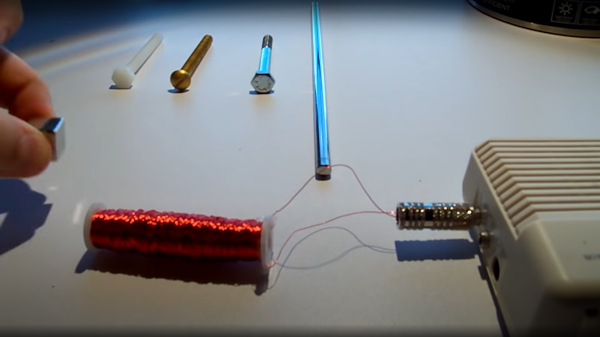
The Barkhausen effect — named after German Physicist Heinrich Barkhausen — is the term given to the noise output produced by a ferromagnetic material due to the change in size and orientation of its discrete magnetic domains under the influence of an external magnetic field. The domains are small: smaller than the microcrystalline grains that form the magnetic material, but larger than the atomic scale. Barkausen discovered that as a magnetic field was brought close to a ferrous material, the local magnetic field would flip around randomly, as the magnetic domains rearranged themselves into a minimum energy configuration and that this magnetic field noise could be sensed with an appropriately arranged pickup coil and an amplifier. In the short demonstration video below, this Barkhausen noise can be fed into an audio amplifier, producing a very illustrative example of the effect.
One example of practical use for this effect is with non-destructive testing and qualification of magnetic structures which may be subject to damage in use, such as in the nuclear industry. Crystalline discontinuities or impurities within a part under examination result in increased localized mechanical stresses, which could result in unexpected failure. The Barkhausen noise effect can be easily leveraged to detect such discontinuities and give the evaluator a sense of the condition of the part in question. All in all, a useful technique to know about!
If you were thinking that the Barkhausen is a familiar name, you may well be thinking about the Barkhausen stability criterion, which is fundamental to describing some of the conditions necessary for a linear feedback circuit to oscillate. We’ve covered such circuits before, such as this dive into bridge oscillators.
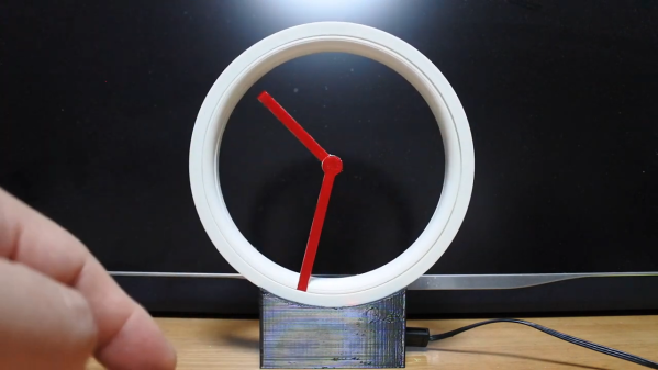
We love projects that make you do a double-take when you first see them. It’s always fun to think you see one thing, but then slowly realize everything is not quite what you expected. And this faceless analog clock is very much one of those projects.
When we first saw [Shinsaku Hiura]’s “Hollow Clock 4,” we assumed the trick to making it look like the hands were floating in space would rely on the judicious use of clear acrylic. But no, this clock is truly faceless — you could easily stick a finger from front to back. The illusion is achieved by connecting the minute hand to the rim of the clock, and rotating the whole outer circumference through a compact 3D printed gear train. It’s a very clever mechanism, and it’s clear that it took a lot of work to optimize everything so that the whole look of the clock is sleek and modern.
But what about the hour hand? That’s just connected to the end of the minute hand at the center of the clock’s virtual face, so how does that work? As it is with most things that appear to be magical, the answer is magnets. The outer rim of the clock actually has another ring, this one containing a pair of neodymium magnets. They attract another magnet located in the very end of the hour hand, dragging it along as the hour ring rotates. The video below shows off the secrets, and it gives you some idea of how much work went into this clock.
We’re used to seeing unique and fun timepieces and other gadgets from [Shinsaku Hiura] — this up-flipping clock comes to mind, as does this custom RPN calculator — but this project is clearly a step beyond.