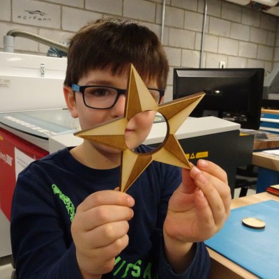
Just to be clear, the primary goal of the Papas Inventeurs (Inventor Dads) was to have the kids make something, have fun, and learn. In that light, they enjoyed a huge success. Four children designed, made, and sold laser-cut napkin rings from a booth at the Ottawa Maker Faire as a fun learning process (English translation, original link in French.) [pepelepoisson] documented the entire thing from beginning to end with plenty of photos. Things started at proof of concept, then design brainstorming, prototyping, manufacture, booth design, and finally sales. While adults were involved, every step was done by the kids themselves.
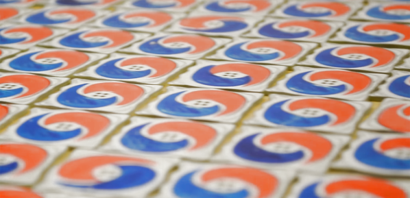
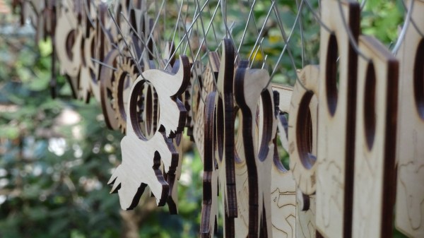
 It all began when the kids were taken to a local fab lab at the École Polytechnique and made some laser-cut napkin holders from plywood for personal use. Later, they decided to design, manufacture, and sell them at the Ottawa Maker Faire. Money for the plywood came from piggy banks, 23 different designs made the cut, and a total of 103 rings were made. A display board and signs made from reclaimed materials rounded out the whole set.
In the end, about 20% of people who visited and showed interest made a purchase, and 60 of the 103 pieces were sold for a profit of $126. Of course, the whole process also involved about 100 hours of combined work between the kids and parents and use of a laser cutter, so it’s not exactly a recipe for easy wealth. But it was an incredibly enriching experience, at least figuratively, for everyone involved.
Possibly the biggest takeaway was the way manufacturing involved much more than just pressing “GO” on a laser cutter. Some pieces needed sanding after laser cutting, and each piece got two coats of varnish. If you missed it, [Bob Baddeley] showed how labor, and not materials, ends up being the most expensive part of a product.