It’s interesting to imagine what computers may have looked like throughout different time periods that precede their portability or even their existence altogether. In the 1950s and ’60s, computers still filled entire rooms, but if the age of the PC had arrived earlier one is left to wonder what might a minimalist mid-century PC might look like.
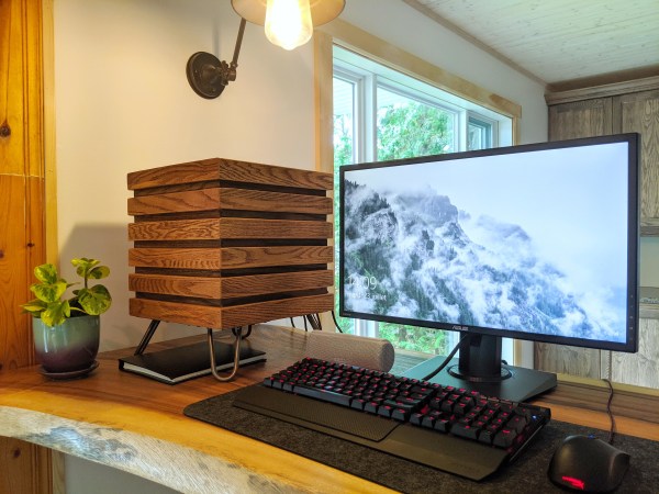
 Well, if we were lucky, it would have looked something like [xmorneau]’s cubical computing creation. This DIY beauty is made of scrap oak and a sexy set of hairpin legs. As hot as it looks, [xmorneau] shouldn’t have to worry about overheating — the bottom is completely open except for an intake fan, there’s another fan at the top that exhausts hot air through a mesh grille, and those lovely little legs elevate it four inches off the desk. Our favorite part (after the legs) has to be the secret lid that blends in beautifully.
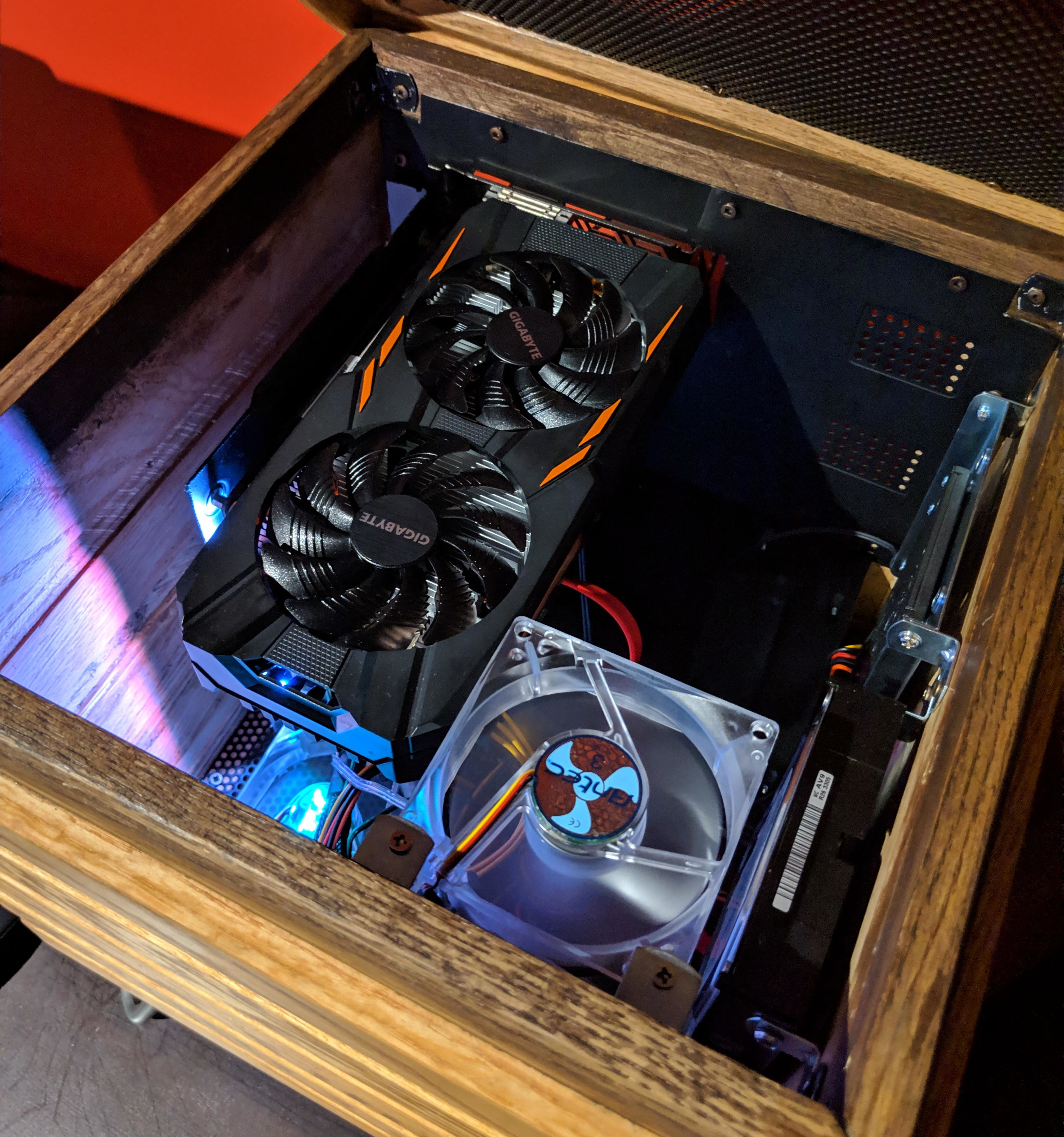
The cube measures 32cm³ (~12.6in³), so [xmorneau] went with a mini-ATX motherboard, but was able to fit in a full-size graphics card. Everything is mounted internally to wood except for the mobo, which is mounted on a panel of sheet metal that makes up the back wall.
We love the way this looks and are glad to see that this build changed [xmorneau]’s opinion of RGB a little bit, because we can’t help but like it both ways.
Too sophisticated for your taste? Check out this LEGO-Minecraft mashup.


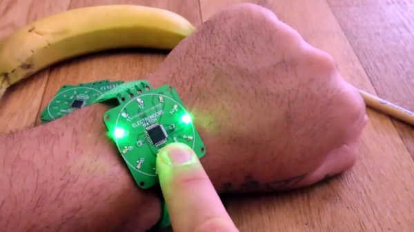
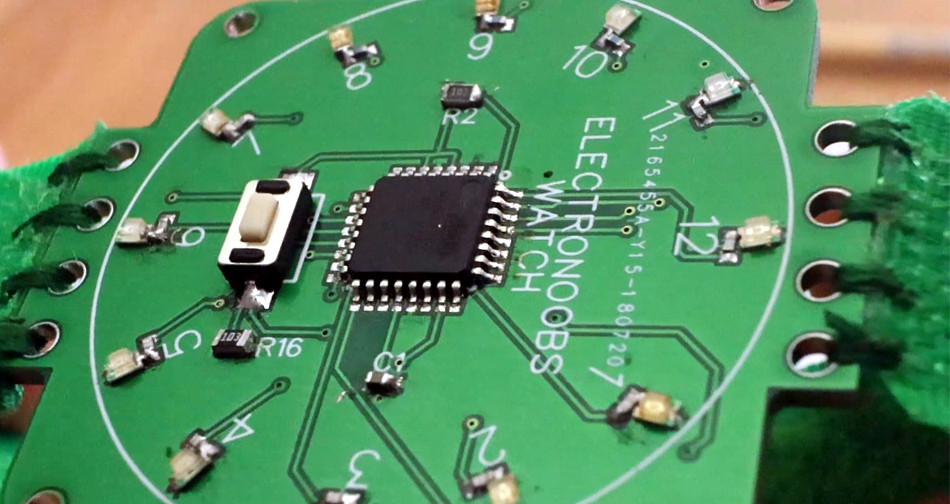
 His source code is available on request but he does detail a neat software trick he uses for rotating the view. It may be confusing for some but as you move through the maze, your viewpoint rotates so that up is always the direction you’re facing. Luckily, the walls surrounding the user can be represented using 8-bits, four for east, west, north, and south, and four more for the corners. The maze is stored as a bitmap and from it, 8-bit values are extracted for the current position, each bit representing a wall around the position. To rotate the walls to match the user’s current orientation, the bits are simply shifted as needed. Then they’re shifted out to set each LED. Check it out in the video below.