We’ve all got calculators on our phones, in our web browsers, and even in the home “assistant” that’s listening in on your conversations all day on the off chance you blurt out a math question is can solve for you. The most hardcore among us might even still have a real calculator kicking around. So in that light, building your own DIY calculator might not seem too exciting. But we can’t deny this Arduino calculator project by [Danko Bertović] would look good sitting on the bench.
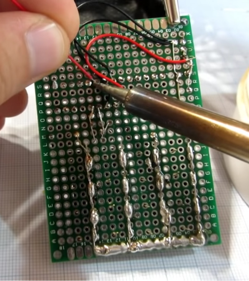 In the video after the break, [Danko] walks us through the creation of the calculator, from placing all the through-hole components to writing the code that pulls it all together. Special attention is given to explaining the wiring, making this is a good project for those just getting started on their digital hacking journey. It also helps that the whole thing is put together on perfboard with jumper wires; no PCB fabrication required for this one.
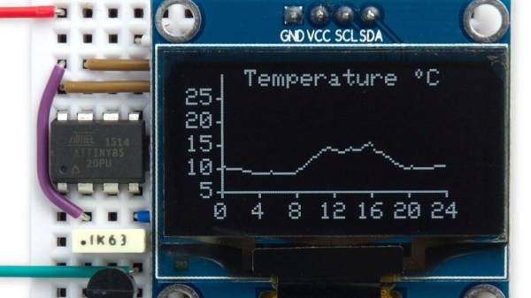
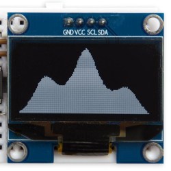
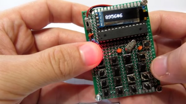
For the user interface, [Danko] is using an array of 17 tactile switches for the keyboard and a very crisp 128×32 I2C OLED display. Beyond the battery, a crystal, and a handful of passive components, that’s about all the support hardware it takes to put this project together. You don’t even need an enclosure: a second piece of perfboard and some standoffs are used to sandwich the battery and fragile wiring inside.
Of course, the star of the show is the ATmega328P microcontroller, which is mounted in a place of honor right under the OLED screen. The chip gets programmed in an Arduino Uno and then transplanted into the calculator, a neat trick if you don’t have a dedicated programmer handy. Given how cheap Arduino clones can be had online, this is becoming a more common practice.
The construction of this calculator reminds us a bit of the DIY Sinclair scientific calculator we looked at over the summer. But if you want to see the peak of homebrew calculator technology, this Raspberry Pi powered build is tough to beat.
Continue reading “Pocket Sized Arduino Calculator Makes A Great First Project”