Right now, we’ve got artistic PCBs, we’ve got #badgelife, and we have reverse-mounted LEDs that shine through the fiberglass substrate. All of this is great for PCBs that are functional works of art. Artists, though, need to keep pushing boundaries and the next step is obviously a PCB that doesn’t look like it has any components at all. We’re not quite there yet, but [Stephan] sent in a project that’s the closest we’ve seen yet. It’s a PCB where all the components are contained within the board itself. A 2D PCB, if you will.
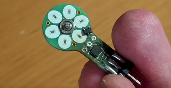
[Stephen]’s project is somewhat simple as far as a #badgelife project goes. It’s a Christmas ornament, powered by two coin cells, hosting an ATTiny25 and blinking two dozen LEDs via Charlieplexing. The PCB was made in KiCAD, with some help from Inkscape and Gimp. So far, so good.
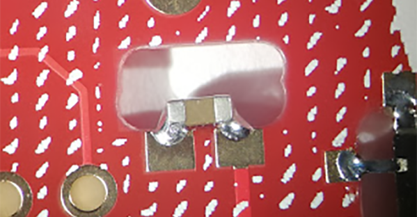
The trick is mounting all the components in this project so they don’t poke out above the surface of the board. This is done by milling a rectangular hole where every part should go and adding castellated pads to one side of the hole. The parts are then soldered in one at a time against these castellated pads, so the thickness of the completed, populated board is just the thickness of the PCB.
The parts used in this project are standard jellybean parts, but there are a few ways to improve the implementation of this project. The LEDs are standard 0805s, but side-emitting LEDs do exist. If you’d like to take this idea further, it could be possible to create a sandwich of PCBs, with the middle layer full of holes for components. These layers of PCBs can then be soldered or epoxied together to make a PCB that actually does something, but doesn’t look like it does. This technique is done in extremely high-end PCBs, but it’s expensive as all get out.
Still, this is a great example of what can be done with standard PCB processes and boards ordered from a random fab house. It also makes for a great Christmas ornament and pushes the boundaries of what can be done with PCB art.
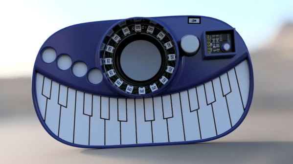
 The unit’s stylus and PCB key interface resemble a