Simple RC To USB Interface

With the radio control hobby arguably larger now than it ever has been in the past, there’s a growing demand for high-fidelity PC simulators. Whether you want to be able to “fly” when it’s raining out or you just want to practice your moves before taking that expensive quadcopter up for real, a good simulator on your computer is the next best thing. But the simulator won’t do you much good if it doesn’t feel the same; you really need to hook your normal RC transmitter up to the computer for the best experience.

[Patricio] writes in to share with us his simple hack for interfacing his RC hardware to his computer over USB. Rather than plugging the transmitter into the computer, his approach allows the receiver to mimic a USB joystick. Not only is this more convenient since you can use the simulator without wires, but it will make sure that the minutiae of your radio hardware (such as response lag) is represented in the simulation.

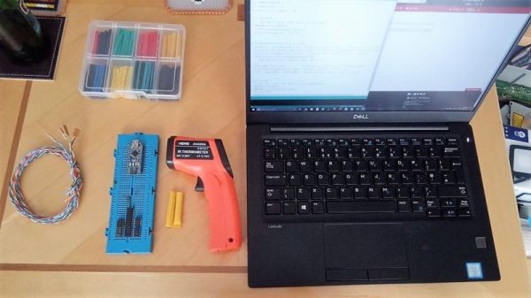
The setup is actually very simple. [Patricio] used the ATtiny85 based Digispark development board because it’s what he had on hand, but the principle would be the same on other microcontrollers. Simply connect the various channels from the RC receiver to the digital input pins. RC receivers are 5 VDC and draw very little current, so it’s even possible to power the whole arrangement from the USB port.

On the software side, the Arduino sketch does about what you expect. It loops through listening for PWM signals on the input pins, and maps that to USB joystick position information. The current code only supports three channels for a simple airplane setup (X and Y for joystick, plus throttle), but it should be easy enough to follow along and add more channels if you needed them for more complex aircraft.

For more information on the intricacies of RC transmitter and receiver interaction, check out this fascinating research on receiver latency.

Casting Tour-De-Force Results In Swashplate For Scale Helicopter

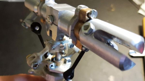
While quadcopters seem to attract all the attention of the moment, spare some love for the rotary-wing aircraft that started it all: the helicopter. Quads may abstract away most of the aerodynamic problems faced by other rotorcraft systems through using software, but the helicopter has to solve those problems mechanically. And they are non-trivial problems, since the pitch of the rotors blades has to be controlled while the whole rotor disk is tilted relative to its axis.

The device that makes this possible is the swashplate, and its engineering is not for the faint of heart. And yet [MonkeyMonkeey] chose not only to build a swashplate from scratch for a high school project, but since the parts were to be cast from aluminum, he had to teach himself the art of metal casting from the ground up. That includes building at least three separate furnaces, one of which was an electric arc furnace based on an arc welder with carbon fiber rods for electrodes (spoiler alert: bad choice). The learning curves were plentiful and steep, including getting the right sand mix for mold making and metallurgy by trial and error.

With some machining help from his school, [MonkeyMonkeey] finally came up with a good design, and we can’t wait to see what the rest of the ‘copter looks like. As he gets there, we’d say he might want to take a look at this series of videos explaining the physics of helicopter flight, but we suspect he’s well-informed on that topic already.

[via r/DIY]

Hacked RC Transmitters Control All The Things

If you have lots of RC creations about, each with their own receiver, you’ll know that the cost of a new one for each project can quickly mount up – despite RC receivers being pretty cheap these days. What if you could use a NRF24L01+ module costing less than $3?

That’s just what [Rudolph] has done for his Hackaday Prize entry, rudRemoteThough many people already spin their own RC link with the NRF24 modules, this sets itself apart by being a complete, well thought out solution, easily scalable to a large number of receivers.

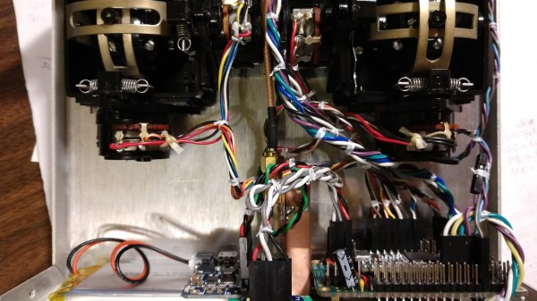
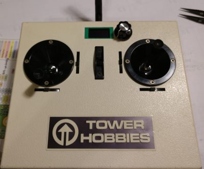
The transmitter can be made of anything to hand; stick an NRF24 module and Teensy inside, some gimbals if needed, and you have a rudRemote transmitter. Gaming controllers, sandwich boxes and piles of laser cut parts are all encouraged options. [Rudolph] used some 40-year-old transmitters for his build – on the outside they remain unchanged, apart from a small OLED and rotary encoder for the function menu. The gimbal connections are simply re-routed to the Teensy I/O.

The protocol used is CRTP (Crazy RealTime Protocol); this is partly because one of the things [Rudolph] wanted to control is a CrazyFlie quadcopter. It’s a protocol that can easily be used to control anything you like, providing it fits into the 29-byte payload space. The CrazyFlie only uses 14 bytes of that, so there’s plenty of headroom for auxiliary functions.

We’d be interested to see the latency of this system – we’ve some surprising results when it comes to measuring cheap RC transmitter latency.

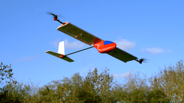
RC Paper Airplane From Guts Of Quadcopter

Mini indoor drones have become an incredibly popular gift in the last few years since they’re both cool and inexpensive. For a while they’re great fun to fly around, until the inevitable collision with a wall, piece of furniture, or family member. Often not the most structurally sound of products, a slightly damaged quad can easily be confined to a cupboard for the rest of its life. But [Peter Sripol] has an idea for re-using the electronics from a mangled quad by building his own RC controlled paper aeroplane.

[Peter] uses the two rear motors from a mini quadcopter to provide the thrust for the aeroplane. The key is to remove the motors from the frame and mount them at 90 degrees to their original orientation so that they’re now facing forwards. This allows the drone’s gyro to remain facing upwards in its usual orientation, and keep the plane pointing forwards.

The reason this works is down to how drones yaw: because half of the motors spin the opposite direction to the other half, yaw is induced by increasing the speed of all motors spinning in one direction, mismatching the aerodynamic torques and rotating the drone. In the case of the mini quadcopter, each of the two rear motors spin in different directions. Therefore, when the paper plane begins to yaw off-centre, the flight controller increases power to the appropriate motor.

Mounting the flight controller and motors to the paper plane can either be achieved using a 3D-printed mount [Peter] created, or small piece of foam. Shown here is the foam design that mounts the propellers at wing level but the 3D printed version has then under the fuselage and flies a bit better.

Making paper planes too much effort? You could always use the one-stroke paper plane folder, or even the paper plane machine gun.

Continue reading “RC Paper Airplane From Guts Of Quadcopter”

Giant F1 Car Is 3D Printed And Radio Controlled

The OpenRC F1 car is a radio control car you can 3D print and assemble yourself. You make the parts, glue them together, and then add your RC gear. That’s all well and good, but could it be done… bigger? [3D Printing Nerd] decided to tackle this one at 4x scale.

It goes without saying that this took some work. The model has to be carved up into sections that would actually fit on the printers to hand. This can take some planning to ensure the parts still come out nicely, as they may be printed in different orientations or with different slicer settings than originally intended.

That’s just the start, though. Once they’re printed, the parts need to be accurately aligned and glued together, which is a whole extra set of challenges. Urethane, epoxy and superglue adhesives are all pressed into service here to get the job done.

It’s a multipart build, as it’s a huge undertaking to 3D print anything on this scale. It’s a great example of taking a fun project, and turning up the silly factor to 11. And of course, at the end of the day, you’ve got a gigantic RC car to play with. Perhaps the only bigger RC cars we’ve seen have been… actual cars.

Glorious Body Of Tracked ‘Mad Mech’ Started As Cardboard

[Dickel] always liked tracked vehicles. Taking inspiration from the ‘Peacemaker’ tracked vehicle in Mad Max: Fury Road, he replicated it as the Mad Mech. The vehicle is remote-controlled and the tank treads are partly from a VEX robotics tank tread kit. Control is via a DIY wireless controller using an Arduino and NRF24L01 modules. The vehicle itself uses an Arduino UNO with an L298N motor driver. Power is from three Li-Po cells.

The real artistic work is in the body. [Dickel] used a papercraft tool called Pepakura (non-free software, but this Blender plugin is an alternative free approach) for the design to make the body out of thin cardboard. The cardboard design was then modified to make it match the body of the Peacemaker as much as possible. It was coated in fiberglass for strength, then the rest of the work was done with body filler and sanding for a smooth finish. After a few more details and a good paint job, it was ready to roll.

There’s a lot of great effort that went into this build, and [Dickel] shows his work and process on his project page and in the videos embedded below. The first video shows the finished Mad Mech being taken for some test drives. The second is a montage showing key parts of the build process.

Continue reading “Glorious Body Of Tracked ‘Mad Mech’ Started As Cardboard”

Single Motor, Single Piece 3D Printed Hovercraft

RC hovercrafts offer all sorts of design options which make them interesting projects to explore. There are dual-motor ones where one motor provides lift while the other does the thrust. For steering, the thrust motor can swivel or you can place a rudder behind it. And there are single-motor ones where one motor does all the work. In that case, the airflow from the motor blades has to be redirected to under the hovercraft somehow, while also being vectored out the back and steered.

[Tom Stanton] decided to make a single-motor hovercraft using only a single 3D printed piece for the main structure. His goals were to keep it as simple as possible, lightweight, and inexpensive. Some of the air from the blades is directed via ducting printed into the structure to the underside while the remainder flows backward past a steering rudder. He even managed to share a bolt between the rudder’s servo and the motor mount. Another goal was to need no support structure for the printing, though he did get some stringing which he cleaned up easily by blasting them with a heat gun.

From initial testing, he found that it didn’t steer well. He suspected the rudder wasn’t redirecting the air to enough of a sideways angle. The solution he came up with was pretty ingenious, switching to a wedge-shaped rudder. In the video below he gives a the side-by-side comparison of the two rudders which shows a huge difference in the angle at which the air should be redirected, and further testing proved that it now steered great.

Another issue he attacks in the video below was a tendency for the hovercraft to dip to one side. He solves this with some iterative changes to the skirt, but we’ll leave it to you to watch the video for the details. The ease of assembly and the figure-eight drift course he demonstrates at the end shows that he succeeded wonderfully with his design goals.

Continue reading “Single Motor, Single Piece 3D Printed Hovercraft”