It used to be that there wasn’t a problem on the average car that couldn’t be solved with a nice set of wrenches, a case of beer, and a long weekend. But the modern automobile has more in common with a spaceship than those vintage rides of yesteryear. Bristling with sensors and electronics, we’re at the point that some high-end cars need to go back to the dealer for even minor repairs. It’s a dark time for the neighborhood grease monkey.
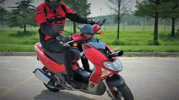
 But for those of us who are more likely to spend their free time working with a compiler than a carburetor, a modern car can be an absolute wonderland. That’s what [TJ Bruno] found when he recently started experimenting with the CAN bus on his 2017 Chevy Cruze. Not only was he able to decode how the different switches and buttons on the dashboard communicated with the vehicle’s onboard systems, he was able to hack in a forward-looking camera that’s so well integrated you’d swear it was a factory option.
The idea started simple enough: using some relays, [TJ] planned on physically switching the video feed going to the Chevy’s dashboard between the stock rear camera and his aftermarket front camera. That’s all well and good, but the car would still only bring up the video feed when the gear selector was put in reverse; not exactly helpful when he’s trying to inch his way into a tight spot. He needed to find a way to bring up the video display when the car was moving forward.
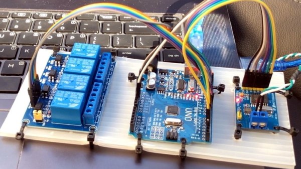
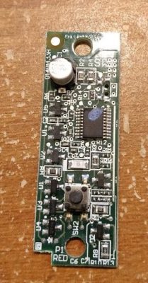
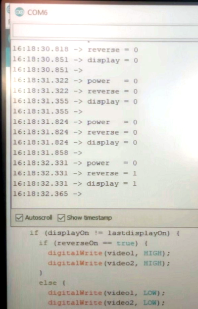
With a PCAN-USB adapter connected to the car’s OBD-II port, he shifted into and out of reverse a few times and noted which messages got transmitted on the network. It wasn’t long before he isolated the proper message, and when he injected it with his laptop, the dashboard display switched over to the backup camera regardless of what gear the car was in. Building on this success, he eventually figured out how to read the status of all the buttons on the car’s dashboard, and programmed an Arduino to listen for the appropriate signals.
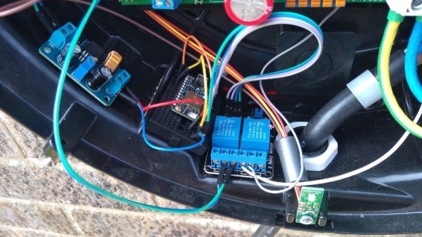
The final piece of the puzzle was combing bringing both of these capabilities, so that went the appropriate button was pressed on the dashboard the Arduino would not only send the signal to turn on the video display, but kick the relays over to switch the camera source. Now [TJ] has a front-facing camera that can be called up without having to kludge together some button or switch that would never match the modern styling of the vehicle’s interior.
A couple years back we saw a similar project to add a backup camera to a Peugeot 207 that was too old to have one from the factory, and more recently we saw how CAN hacking can allow you to fight back when your car’s touch screen interface robs you of simple pleasures like pushing buttons and turning knobs.
Continue reading “Sniffing CAN To Add New Features To A Modern Car” →