Crashing one’s bike is a childhood rite of passage, one that can teach valuable lessons in applied physics. Assuming the kid is properly protected and the crash is fairly tame, scrapes and bruises are exchanged for the wisdom to avoid sand and gravel patches, and how to avoid a ballistic dismount by not applying the front brakes harder than or before the rear brakes.
But for many of us, those lessons were learned long ago using a body far more flexible than the version we’re currently in, and the stakes are higher for a bike ride that includes braking mistakes. To help with that, [Tom Stanton] has been working on anti-lock brakes for bicycles, and in the process he’s learned a lot about the physics and engineering of controlled deceleration.
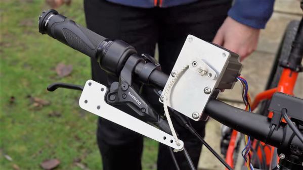
It seems a simple concept – use a sensor to detect when a wheel is slipping due to decreased friction between the tire and the roadway, and release braking force repeatedly through an actuator to allow the driver or rider to maintain control while stopping. But that abstracts away a ton of detail, which [Tom] quickly got bogged down in. With a photosensor on the front wheel and a stepper motor to override brake lever inputs, he was able to modulate the braking force, but not with the responsiveness needed to maintain control. Several iterations later, [Tom] hit on the right combination of sensors, actuators, and algorithms to make a decent bike ABS system. The video below has all the details of the build and testing.
[Tom] admits bike ABS isn’t much of an innovation. We even covered an Arduino-instrumented bike that was to be an ABS testbed a few years back. But it’s still cool to see how much goes into anti-lock systems.
We all know CERN as that cool place where physicists play with massive, superconducting rings to smash atoms and subatomic particles to uncover secrets of matter in the Universe. To achieve this aim, they need to do a ton of research in other areas, such as development of special particle detectors.
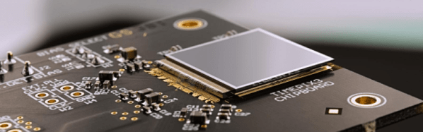
While such developments are essential to the core research needs of the Centre, they also lead to spinoff applications for the benefit of society at large. One such outcome has been the Medipix Collaborations – a family of read-out chips for particle imaging and detection that can count single photons, allowing X-rays and gamma rays to be converted to electrical signals. It may not be possible for us hackers to get our hands on these esoteric sensors, but these devices are pretty interesting and deserve a closer look. Medipix sensors work like a camera, detecting and counting each individual particle hitting the pixels when its electronic shutter is open. This enables high-resolution, high-contrast, noise hit free images – making it unique for imaging applications.
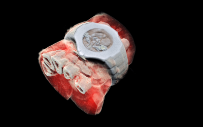
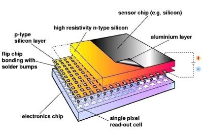
Some months back, CERN announced the first 3D color X-ray of a human made possible using the Medipix devices. The result is a high-resolution, 3D, color image of not just living structures like bones, muscular tissues and vessels, but metal objects too like the wrist watch, seen in the accompanying photograph. The Medipix sensors have been in development since the 1990’s and are presently in their 4th “generation”. Each chip consists of a top semiconducting sensor array, made from gallium arsenide or cadmium telluride. The charge collected by each pixel is transported to the CMOS ASIC electronics via “bump bonds”. The integration is vertical, with each sensing pixel connected via the bump bond to an analog section followed by a digital processing layer. Earlier versions were limited, by technology, in their tiling ability for creating larger matrices of multiple sensors. They could be abutted on three sides only, with the fourth being used for on-chip peripheral logic and wire-bond pads that permit electronic read-out. The latest Medipix4 Collaboration, still under some development, eliminates this short coming. Through-silicon-via (TSV) technology provides the possibility of reading the chips through copper-filled holes that bring the signals from the front side of the chip to its rear. All communication with the pixel matrix flows through the rear of the chip – the peripheral logic and control elements are integrated inside the pixel matrix.
The Analog front end consists of a pre-amplifier followed by a window discriminator which has upper and lower threshold levels. The discriminator has four bits for threshold adjustment as well as polarity sensing. This allows the capture window to be precisely set. The rest of the digital electronics – multiplexers, shift registers, shutter and logic control – helps extract the data.
Further development of the Medipix (Tech Brief, PDF) devices led to a separate version called Timepix (Tech Brief, PDF). These new devices, besides being able to count photons, are capable of two additional modes. The first mode records “Time-Over-Threshold”, providing rough analog information about the energy of the photon. It does this by counting clock pulses for the duration when the signal stays above the discrimination levels. The other mode, “Time of Arrival”, measures arrival time of the first particle to impinge on the pixel. The counters record time between a trigger and detection of radiation quanta with energy above the discrimination level, allowing time-of-flight applications in imaging.
Medipix3 pixel schematic
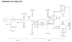
Timepix2 pixel schematic
Besides medical imaging, the devices have applications in space, material analysis, education and of course, high energy physics. Hopefully, in a few years, hackers will lay their hands on these interesting devices and we can get to know them better. At the moment, the Medipix website has some more details and data sheets if you would like to dig deeper. For an overview on the development of such single photon detectors, check out this presentation from CERN – “Single X-Ray Photon Counting Systems: Existing Systems, Systems Under Development And Future Trends” (PDF).
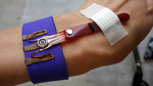
Pivots for e-textiles can seem like a trivial problem. After all, wires and fabrics bend and flex just fine. However, things that are worn on a body can have trickier needs. Snap connectors are the usual way to get both an electrical connection and a pivot point, but they provide only a single conductor. When [KOBAKANT] had a need for a pivoting connection with three electrical conductors, they came up with a design that did exactly that by using a flexible circuit board integrated to a single button snap.
This interesting design is part of a solution to a specific requirement, which is to accurately measure hand movements. The photo shows two strips connected together, which pivot as one. The metal disk near the center is a magnet, and underneath it is a Hall effect sensor. When the wrist bends, the magnet is moved nearer or further from the sensor and the unit flexes and pivots smoothly in response. The brief videos embedded below make it clear how the whole thing works.
There’s no doubting the wonders that micro-electromechanical systems (MEMS) technology have brought to the world. With MEMS chips, your phone can detect the slightest movement, turning it into a sensitive sensor platform that can almost anticipate what you’re going to do next. Actually, it’s kind of creepy when you think about it.
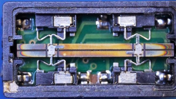
But before nano-scale MEMS inertial sensing came along, lots of products needed to know their ups from their downs, and many turned to products such as this vibrating piezoelectric gyroscope that [Kerry Wong] found in an old camcorder. The video below shows a teardown of the sensor, huge by MEMS standards but still a marvel of micro-engineering. The device is classified as a Coriolis vibratory gyroscope (CVG) which, as the name implies, uses the Coriolis effect to sense rotation. In this device, [Kerry] found that a long, narrow piezoelectric element spans the long axis of the sensor, suspended from what appears to be four flexible arms. [Kerry] probed the innards of the sensor while powered up and discovered a 22 kHz signal on the piezo element; this vibrates the bar in one plane so that when it rotates, it exerts a force on the support arms that can be detected. Indeed, [Kerry] hooked the output of the sensor to a wonderfully old-school VOM whose needle wiggled with the slightest movement of the sensor.
Sadly, MEMS made this kind of sensor obsolete, but we appreciate the look under the hood. And really, MEMS chips are using the same principle to detect motion, just on a much smaller scale. Want the MEMS basics? [Al] has you covered.
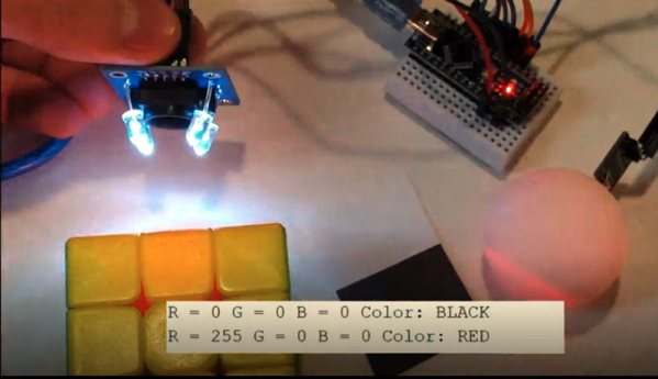
When [millerman4487] bought a TCS230-based color sensor, he was expecting a bit more documentation. Since he didn’t get it, he did a little research and some experimentation and wrote it up to help the rest of us.
The TCS3200 uses an 8×8 array of photodiodes. The 64 diodes come in four groups of 16. One group has a blue filter, one has green and the other has a red filter. The final set of diodes has no filter at all. You can select which group of diodes is active at any given time.
So you just got something like an Arduino or Raspberry Pi kit with a few sensors. Setting up temperature or motion sensors is easy enough. But what are you going to do with all that data? It’s going to need storage, analysis, and summarization before it’s actually useful to anyone. You need a dashboard!
But even before displaying the data, you’re going to need to store it somewhere, and that means a database. You could just send all of your data off into the cloud and hope that the company that provides you the service has a good business model behind it, but frankly the track records of even the companies with the deepest pockets and best intentions don’t look so good. And you won’t learn anything useful by taking the easiest way out anyway.
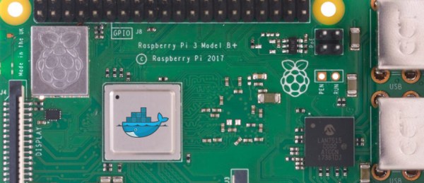
Instead, let’s take the second-easiest way out. Here’s a short tutorial to get you up and running with a database backend on a Raspberry Pi and a slick dashboard on your laptop or cellphone. We’ll be using scripts and Docker to automate as many things as possible. Even so, along the way you’ll learn a little bit about Python and Docker, but more importantly you’ll have a system of your own for expansion, customization, or simply experimenting with at home. After all, if the “cloud” won’t let you play around with their database, how much fun can it be, really?
Have you ever wished you could see in the RF part of the radio spectrum? While such a skill would probably make it hard to get a good night’s rest, it would at least allow you to instantly see dead spots in your WiFi coverage. Not a bad tradeoff.
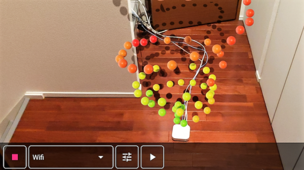
Unwilling to go full [Geordi La Forge] to be able to visualize RF, [Ken Kawamoto] built the next best thing – an augmented-reality RF signal strength app for his smartphone. Built to aid in the repositioning of his router in the post-holiday cleanup, the app uses the Android ARCore framework to figure out where in the house the phone is and overlays a color-coded sphere representing sensor data onto the current camera image. The spheres persist in 3D space, leaving a trail of virtual breadcrumbs that map out the sensor data as you warwalk the house. The app also lets you map Bluetooth and LTE coverage, but RF isn’t its only input: if your phone is properly equipped, magnetic fields and barometric pressure can also be AR mapped. We found the Bluetooth demo in the video below particularly interesting; it’s amazing how much the signal is attenuated by a double layer of aluminum foil. [Ken] even came up with an Arduino with a gas sensor that talks to the phone and maps the atmosphere around the kitchen stove.
The app is called AR Sensor and is available on the Play Store, but you’ll need at least Android 8.0 to play. If your phone is behind the times like ours, you might have to settle for mapping your RF world the hard way.

 Some months back, CERN announced
  The Analog front end consists of a pre-amplifier followed by a window discriminator which has upper and lower threshold levels. The discriminator has four bits for threshold adjustment as well as polarity sensing. This allows the capture window to be precisely set. The rest of the digital electronics – multiplexers, shift registers, shutter and logic control – helps extract the data.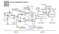
 Unwilling to go full [Geordi La Forge] to be able to visualize RF, [Ken Kawamoto] built the next best thing –








