If there’s one thing we like around here more than seeing an improved version of a project we’ve already covered, it’s when the improvements make the original project cheaper. In the case of this LED ring light for pots and encoders, not only is it cheaper than its predecessors, it’s better looking and easier to integrate into your projects.
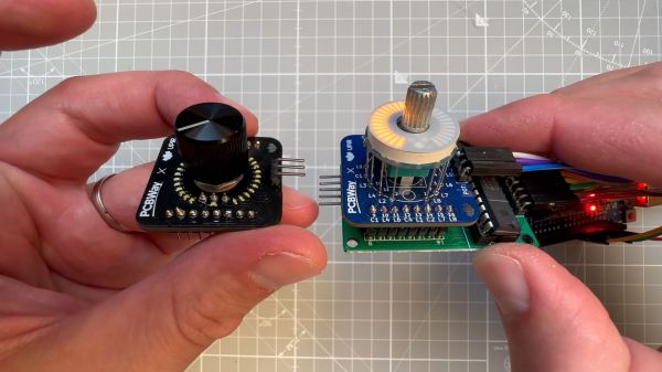
Right from its start, [upir]’s “Pimp My Pot” project has been all about bringing some zazzle to rotary controls. Knobs with a pointer and a scale on the panel are okay — especially when they go to eleven — but more lights mean more fun. The fun comes at a price, though; the previous version of “PMP” used an off-the-shelf LED ring light with a unit cost of about $10. Not the end of the world, perhaps, but prohibitive, and besides, where’s the fun in just buying a component specifically made for rotary control indication?
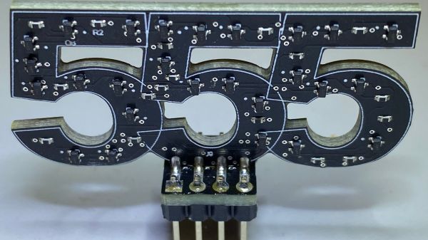
The new version shown in the video below is pin-compatible with the driver board [upir] used for the previous version, which is based on the MAX7219 display driver. Modifying the previous board to accommodate 32 white 0402 LEDs over a 270° arc was no mean feat. [upir] covers both creating the schematic and the PCB layout in some detail, providing his usual trove of tool-chain tips for minimizing the amount of manual work needed.
Wisely, [upir] chose to get his boards assembled by the vendor; getting all those LEDs to line up perfectly is a job best left to the robots. While the board is designed for use with pots that mount on either side, we much prefer mounting the pot’s shaft through the board, as it keeps the LEDs closer to the knob. The final price per board works out to about $6.30 in quantities of ten and falls to a trivial $1.70 each for lots of 1,000. Pretty sweet savings on a pretty sweet-looking build.
This is a cool use of a ring of LEDs, but if you prefer the finger kind, you can make that, too. You can do it the easy way or the hard way.
Continue reading “Pimp My Pot Redux, Now Cheaper And Even Better” →