About two decades ago there was a quiet revolution in electronics which went unnoticed by many, but which overturned a hundred years of accepted practice. You’d have noticed it if you had a mobile phone, the charger for your Nokia dumbphone around the year 2000 would have been a weighty device, while the one for your feature phone five years later would have been about the same size but relatively light as a feather. The electronics industry abandoned the mains transformer from their wall wart power supplies and other places in favour of the much lighter and efficient switch mode power supply. Small mains transformers which had been ubiquitous in electronics projects for many years, slowly followed suit.
Coils Of Wire, Doing Magic With Electrons
A transformer works through transferring alternating electrical current into magnetic flux by means of a coil of wire, and then converting the flux back to electric current in a second coil. The flux is channeled through a ferromagnetic transformer core made of iron in the case of a mains transformer, and the ratio of input voltage to output voltage is the same as the turns ratio between the two. They provide a safe isolation between their two sides, and in the case of a mains transformer they often have a voltage regulating function as their core material is selected to saturate should the input voltage become too high. The efficiency of a transformer depends on a range of factors including its core material and the frequency of operation, with transformer size decreasing with frequency as efficiency increases.
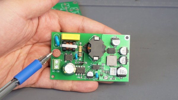
When energy efficiency rules were introduced over recent decades they would signal the demise of the mains transformer, as the greater efficiency of a switch-mode supply became the easiest way to achieve the energy savings. In a sense the mains transformer never went away, as it morphed into the small ferrite-cored part running at a higher frequency in the switch-mode circuitry, but it’s fair to say that the iron-cored transformers of old are now a rare sight. Does this matter? It’s time to unpack some of the issues surrounding a small power supply. Continue reading “Parts We Miss: The Mains Transformer”