Vacuum Chamber Gets Automation

[Nick Poole] does a lot of custom work with vacuum tubes — so much so that he builds his own vacuum tubes of various shapes, sizes, and functions right on his own workbench. While the theory of vacuum tubes is pretty straightforward, at least to those of us who haven’t only been exposed to semiconductors, producing them requires some specialized equipment. A simple vacuum won’t get you all the way there, and the complexity of the setup that’s needed certainly calls for some automation.

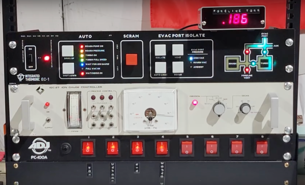
The vacuum system that [Nick] uses involves three sections separated by high-vacuum valves in order to achieve the pressures required for vacuum tube construction. There’s a rough vacuum section driven by one pump, a high vacuum section driven by a second pump, and a third section called the evac port where the tube is connected. Each second must be prepared properly before the next section can be engaged or disengaged. An Arduino Pro is tasked with all of this, chosen for its large amount of ADC inputs for the instrumentation monitoring the pressures in each section, as well as the digital I/O to control the valves and switches on the system.

The control system is built into a 19-inch equipment rack with custom faceplates which outline the operation of the vacuum system. A set of addressable LEDs provide the status of the various parts of the system, and mechanical keyboard switches are used to control everything, including one which functions as an emergency stop. The automation provided by the Arduino reduces the chances for any mistakes to be caused by human error, allows the human operator to focus on other tasks like forming the glass, and can also react much faster to any potentially damaging situations such as the high-pressure pump being exposed to atmospheric pressure.

As you can probably tell, [Nick] is pretty passionate about this stuff — last year he gave a talk at the Hackaday Supercon that went over all the intricacies of building one’s own vacuum tubes.

Continue reading “Vacuum Chamber Gets Automation”

Binary Calculator For All 0b10 Types

You know the old joke: There are 10 types of people in the world — those who understand binary, and those who don’t. Most of us on Hackaday are firmly in the former camp, which is why projects like this circuit sculpture binary calculator really tickle our fancies.

Inspired by the brass framework and floating component builds of [Mohit Bhoite], [dennis1a4] decided to take the plunge into circuit sculpture in an appropriately nerdy way. He wisely decided on a starter build, which was a simple 555 timer circuit, before diving into the calculator. Based on an ATMega328P in a 28-pin DIP, the calculator is built on an interesting hybrid platform of brass wire and CNC-routed wood. The combination of materials looks great, and we especially love the wooden keycaps on the six switches that make up the keyboard. There’s also some nice work involved in adapting the TLC5928 driver to the display of 16 discrete LEDs; suspended as it is by fine magnet wires, the SSOP chip looks a bit like a bug trapped in a spider web.

Hats off to [dennis1a4] for a great entry into our soon-to-conclude Circuit Sculpture Contest. The entry deadline is (today!) November 10, so it might be a bit too late for this year. But rest assured we’ll be doing this again, so take a look at all this year’s entries and start thinking about your next circuit sculpture build.

Continue reading “Binary Calculator For All 0b10 Types”

Soldering Practice Kit Remains Useful After Completion

Unsatisfied with the standard fare of soldering practice kits that offer little to no purpose once they’re built, [Jim Heaney] decided to take matters into his own hands and design an easy-to-assemble kit for his class that, once put together, becomes the handiest of tools in any maker’s workbench: a functional voltmeter.

At the heart of the kit is a standard Atmega 328P microcontroller. While he could’ve picked something smaller or cheaper, not only does the bulky part make for easier soldering, [Jim] reasons that it’s a chip that’s easy to repurpose should his students want to build something like a breadboard Arduino, for example. The voltmeter has a fixed measurement range from 0 to 100 VDC, the only switches on the board are for powering it on and a hold button, which freezes the value currently being shown in the three-digit, seven-segment display.

Along with selling his kit to other makers and educators, [Jim] also hopes that his project encourages others to design similar soldering kits which favor some sort of function rather than getting binned once there’s solder on all the pads, as well as part variety and documentation. If you’re on the other end of the soldering spectrum, then why not challenge your skills soldering on a time limit?

PrintEye Gives You Stats In A Blink

Once upon a time, most things were single-purpose, like the pocket watch. Then somebody made a watch with a date function, and next thing you know, we had TV/VCR combos and Swiss army knives. Now, people pull computers out of their pockets just to check the time or the bed temperature of their RepRap.

[Owen]’s antidote for this multi-function madness is PrintEye, a simple interface that queries his printer and displays its vital signs on a pair of OLED peepers. It’s a parts bin special, and you know how much we love those. PrintEye connects to the Duet controller over UART, and does its firmware whispering with an ATMega328P. The ‘Mega sends a single M-command and gets back all the status and temperature data in JSON format. Then it parses the info and displays it on twin OLED screens.

Want to make one? [Owen]’s got all the files you need over on IO, but offers no hand-holding services. If you’ve never spun a board before, this could be your introduction. Have to have an internet connection? Check out the Octoprint monitor that inspired PrintEye.

Resistance Is Futile, You Want This LED Cube

We’re suckers for a good desk toy here at Hackaday, so this 2019 Hackaday Prize entry from [Jack Flynn] certainly caught our eye. The idea is that by using professionally manufactured dual layer PCBs and only surface mount components, you can create a cube that has an LED matrix on each face and all of the electronics hidden within. We’re not entirely sure if there’s any practical application for such a device, but we know we’d certainly like to have one blinking madly away on our shelf regardless.

Before having any of the PCBs manufactured, [Jack] is putting a considerable amount of thought into the design so he doesn’t end up painting himself info a corner (which is of course eight times as bad when you’re building a cube). By importing the PCB files into OnShape, he’s able to “assemble” a virtual representation of the final product to better understand how everything will fit together. He wants to limit the amount of times the cube will need to be pulled apart, so everything from how it will sit in its 3D printed cradle to the placement of breakaway tabs that ensure the internal power switch is accessible are being carefully planned out.

The current design puts the “brains” on the bottom board, with every other panel holding a daisy-chained MAX7219 to drive its own individual 64 LED matrix. Initially the dimensions of the ATmega328p powered cube will be 42 x 42 x 42 mm, with a total of 384 LEDs. Ultimately, [Jack] hopes the modular nature of the design could allow the size of the cube to be increased, or perhaps even take on a different shape entirely.

Generally the LED cubes we see are of the more wiry variety, so it’s particularly interesting when they take on solid forms like this one. Given the nearly universal popularity of blinking LED gadgets, we think this particular project is well positioned to make the leap from one-off hack to a commercial product.

Continue reading “Resistance Is Futile, You Want This LED Cube”

Kinetic Sculpture Achieves Balance Through Machine Learning

We all know how important it is to achieve balance in life, or at least so the self-help industry tells us. How exactly to achieve balance is generally left as an exercise to the individual, however, with varying results. But what about our machines? Will there come a day when artificial intelligences and their robotic bodies become so stressed that they too will search for an elusive and ill-defined sense of balance?

We kid, but only a little; who knows what the future field of machine psychology will discover? Until then, this kinetic sculpture that achieves literal balance might hold lessons for human and machine alike. Dubbed In Medio Stat Virtus, or “In the middle stands virtue,” [Astrid Kraniger]’s kinetic sculpture explores how a simple system can find a stable equilibrium with machine learning. The task seems easy: keep a ball centered on a track suspended by two cables. The length of the cables is varied by stepper motors, while the position of the ball is detected by the difference in weight between the two cables using load cells scavenged from luggage scales. The motors raise and lower each side to even out the forces on each, eventually achieving balance.

The twist here is that rather than a simple PID loop or another control algorithm, [Astrid] chose to apply machine learning to the problem using the Q-Behave library. The system detects when the difference between the two weights is decreasing and “rewards” the algorithm so that it learns what is required of it. The result is a system that gently settles into equilibrium. Check out the video below; it’s strangely soothing.

We’ve seen self-balancing systems before, from ball-balancing Stewart platforms to Segway-like two-wheel balancers. One wonders if machine learning could be applied to these systems as well.

Continue reading “Kinetic Sculpture Achieves Balance Through Machine Learning”

Playing Pong With Micro:bits!

Where would the world be today without Pong, perhaps a lot less fun? For people like [Linker3000] the game is an inspiration toward teaching the next generation of hackers to build and play their own version using Micro:bits as controllers!

Aiming for doing all manner of diligence, [Linker3000] says the code can simply be uploaded to an Arduino — foregoing throwing together a circuit of your own — if you want to jump right into things. For the workshop environment, this setup uses composite video outputs — but this shouldn’t be an issue as most TVs still retain these inputs.

Once built — or sketch uploaded — the Micro:bit paddles can be connected to the ATmega328p and played like an old-school controller, but [Linker3000] has enabled Bluetooth control of the paddles’ A and B buttons via the Bitty app. Additionally — if wires really aren’t your thing and Bluetooth is too new-school for such an old game — a second Micro:bit can control the wired paddle using their built-in radio, provided they’re configured accordingly.

On top of Pong, there are also squash and soccer game modes! Check out the demo after the break.

Continue reading “Playing Pong With Micro:bits!”