Bluetooth RC Car Packs In A Few Sensors

Have you ever been walking around the house, desperate to know the ambient temperature, humidity, and barometric pressure? Have you ever wanted to capture that data with a small remote-controlled platform? If so, this project from [TUENHIDIY] will be exactly what you’ve been looking for. 

The little remote-control car is built around a Seeed Wio Terminal. This is a microcontroller platform that comes with a screen already attached, along with wireless hardware baked in and Grove connectors for hooking up external modules. Thus, the car adds a DHT11 temperature and humidity sensor, along with a BMP280 air pressure sensor using the Grove connectors.

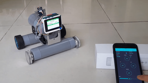
Driving the car is done via a Blynk smartphone app that communicates with the Wio Terminal. Small DC motors at each wheel are driven via a DFRobot quad-motor shield. With the built-in screen, the RC car displays commands received from the smartphone app, as well as the temperature, humidity and pressure in the immediate environment.

We really like the simple PVC-based chassis design, and it’s a straightforward project that demonstrates how to build a Bluetooth-controlled car. Data collected by the sensors is also visible on the smartphone app, so if you need to sample conditions in the next room without getting off the couch, you could do that pretty easily.

Projects like these are a good way to get familiar with working with motors and sensors. It’d be a great base for simple robotics development, too. We’ve featured builds from [TUENHIDIY] before, too, like this great rotary plotter that can draw on bottles. Video after the break.

Continue reading “Bluetooth RC Car Packs In A Few Sensors”

Mini-lathe carriage wheel

Improving A Mini-Lathe With A Few Clever Hacks

Like many budget machinists, the delightfully optimistically named [We Can Do That Better] had trouble with some of the finer controls on his import mini-lathe. But rather than suffer through it, he chose to rectify the machine’s shortcomings and in the process, teach everyone a bunch of great tips.

[We Can Do That Better]’s lathe retrofit focused on the carriage handwheel, which appears to lack proper bearings and wobbles around in a most imprecise manner. On top of that, the gearing of the drive made for an unsatisfying 19 mm of carriage travel per revolution of the handwheel. A single gear change made that an even 20 mm per rev, which when coupled with a calibrated and indexed handwheel ring greatly simplifies carriage travel measurements.

While the end result of the build is pretty great in its own right, for our money the best part of the video is its rich collection of machinist’s tips. The use of a wooden dowel and a printed paper template to stand in for a proper dividing head was brilliant, as was using the tailstock of the lathe to drive an engraving tool to cut the index lines. We’ve seen the use of a Dremel tool mounted to the toolpost to stand in for a milling machine before, but it’s always nice to see that trick used. And the mechanism for locking the dial to the handwheel was really clever, too.

Considering a mini-lathe? As encouraging as [We Can Do That Better]’s experience may be, it might be wise to take a deep dive into the pros and cons of such a machine.

Continue reading “Improving A Mini-Lathe With A Few Clever Hacks”

OpenGL Machine Learning Runs On Low-End Hardware

If you’ve looked into GPU-accelerated machine learning projects, you’re certainly familiar with NVIDIA’s CUDA architecture. It also follows that you’ve checked the prices online, and know how expensive it can be to get a high-performance video card that supports this particular brand of parallel programming.

But what if you could run machine learning tasks on a GPU using nothing more exotic than OpenGL? That’s what [lnstadrum] has been working on for some time now, as it would allow devices as meager as the original Raspberry Pi Zero to run tasks like image classification far faster than they could using their CPU alone. The trick is to break down your computational task into something that can be performed using OpenGL shaders, which are generally meant to push video game graphics.

An example of X2’s neural net upscaling.

[lnstadrum] explains that OpenGL releases from the last decade or so actually include so-called compute shaders specifically for running arbitrary code. But unfortunately that’s not an option on boards like the Pi Zero, which only meets the OpenGL for Embedded Systems (GLES) 2.0 standard from 2007.

Constructing the neural net in such a way that it would be compatible with these more constrained platforms was much more difficult, but the end result has far more interesting applications to show for it. During tests, both the Raspberry Pi Zero and several older Android smartphones were able to run a pre-trained image classification model at a respectable rate.

This isn’t just some thought experiment, [lnstadrum] has released an image processing framework called Beatmup using these concepts that you can play around with right now. The C++ library has Java and Python bindings, and according to the documentation, should run on pretty much anything. Included in the framework is a simple tool called X2 which can perform AI image upscaling on everything from your laptop’s integrated video card to the Raspberry Pi; making it a great way to check out this fascinating application of machine learning.

Truth be told, we’re a bit behind the ball on this one, as Beatmup made its first public release back in April of this year. It might have flown under the radar until now, but we think there’s a lot of potential for this project, and hope to see more of it once word gets out about the impressive results it can wring out of even the lowliest hardware.

[Thanks to Ishan for the tip.]

Mechanical 7-segment display

A One-Servo Mechanical Seven-Segment Display

The seven-segment display may be a bit prosaic after all these years, but that doesn’t mean there aren’t ways to spice it up. Coming up with a mechanical version of the typical photon-based display is a popular project, of which we’ve seen plenty of examples over the years. But this seven-segment display is quite a mechanical treat, and a unique way to flip through the digits.

With most mechanical displays, we’re used to seeing the state of each segment changed with some kind of actuator, like a solenoid or servo. [Shinsaku Hiura] decided on a sleeker design using a 3D-printed barrel carrying one cam for each segment. Each hinged segment is attached to an arm that acts as a follower, riding on its cam and flipping on or off in a set pattern. Which digit is displayed depends on the position of the barrel, which is controlled with a single servo and a pair of gears. It trades mechanical complexity for electrical simplicity and overall elegance, and as you can see from the video below, it’s pretty snappy.

We think the best part of this build is figuring out the shape of the cams. We wonder how they compare to the cam profiles in [Greg Zumwalt]’s mechanical display; it uses two separate discs with grooves, but the principle is pretty much the same.

Continue reading “A One-Servo Mechanical Seven-Segment Display”

Peek Behind The Curtains: Conference Badge Design

In the before-times, back when we could have in-person Hackaday Supercons, there was always the problem of the badge. Making a few hundred small electronic thingies, for a smart but broad range of hackers, is tricky. We always want it to do something all on its own, but also ideally to allow enough free range that the motivated badge hacker can make it into something exquisite. Add in the fact that some attendees are hardware types and some are software types, and toss in a price constraint too. Oh, and it has to look good. Tough problem.

Here’s one extreme solution: the badge at the first Supercon. Faced with essentially zero budget and a tight time constraint, the Hackaday team punted — and produced a prototype board, but had tons of parts on hand for everyone to draw from. And the Hackaday crowd delivered. This was the badge that demonstrates what happens if you leave everything open.

Contrast with the 2018 Belgrade and Supercon badges, which were essentially the same except for color. Here, the hardware interface was limited to a 9-pin header, but the badge itself was a fully functional microcomputer, complete with keyboard and screen. Most of the hacks were written in the native BASIC, though a few hearty souls played around with the alternative CP/M system. This was our most software badge.

Our last in-person badge, the 2019 Supercon badge, was free rein for both hardware and software hackers. The whole thing was based on an FPGA, with completely custom gateware written by Sprite_tm running RISC-V, but based loosely on the Z80 architecture. This was probably also the badge with the highest hurdle to hackers, but you all came through with inventive hardware add-ons, but also a team that came through with a custom Linux OS running on this never-before-seen virtual environment, enabled by a hardware SDRAM cartridge hack.

And finally, even before the global supply crisis, even a tight-knit conference like ours could stock-out the world’s supply of a given component. The untold story of the 2016 Belgrade badge is that Voja Antonic bought out the world’s supply of Kingbright 8×8 common-cathode LED matrixes, and had to redesign the board in the last minute to incorporate the common-anode parts too. (Or was it vice-versa?) Lesson learned, the 2016 Supercon badge traded out the LED modules for discrete LEDs. Not gonna stock out on red LEDs.

So that’s a long-winded introduction to Thomas Flummer’s unofficial Remoticon 2 badges. With the parts crisis and a virtual conference, you’re on your own to source the badge. Splitting the freedom vs. in-built functionality problem like Samson, he’s got two boards — one a breadboard and the other fully populated. And like all his badges, they both look great. If you manage to get one made by Remoticon next week, be sure to show it off in the Bring-a-Hack. And if you don’t get it in time, bring it by in person to the 2022 Supercon!

Using VHDL To Generate Discrete Logic PCB Designs

VHDL and Verilog are hardware description languages, used to describe and define logic circuits. They’re typically used to design ASICs and to program FPGAs, essentially using software to define hardware. However, [Tim] has done something altogether quite creative, creating tools to take VHDL and Verilog and spit out PCB designs for discrete logic. 

Yes, you read that correctly. The basic idea is to take VHDL source code, and then make a PCB layout that implements the desired logic using resistor-transistor logic. From there, the PCB design files can be shipped off to a manufacturer for pick-and-place assembly at a fraction of the cost of producing a bespoke ASIC.

The drawbacks are obvious; tons of individual discrete parts are required, the size penalty is hilariously bad, and power usage is almost certainly orders of magnitude higher than doing the same logic on an ASIC or even FPGA. Oh, and everything’s much slower, too.

However, as an academic exercise or simply for fun, it’s an awesome bit of work. The idea that one can define a complicated logic circuit and have a PCB implementing the logic whipped up by automated tools is amazing, and we absolutely want to see more of this type of thing.

We’ve seen similar work done with VHDL synthesis into 74-series logic design. If you’ve been developing your own fancy digital-logic-fu, be sure to drop us a line!

[Thanks to Yann Guidon for the tip!]

Omnirotor flies over obstacles with its gimballed, caged, coaxial rotors.

Gimballed Omnirotor Goes Over Great Obstacles

What can drive on the ground, hop in the air, and continuously move its coaxial rotor assembly without ever having to reset its position? The answer is [New Dexterity]’s Omnirotor All-Terrain Platform.

Although still very much a prototype, the video below the break shows that the dexterity claimed by Omnirotor isn’t just a lot of hype. Weaving through, around, and over obstacles is accomplished with relative ease by way of a coaxial rotor configuration that’s sure to turn some heads.

Omnirotor flies over obstacles with its gimballed, caged, coaxial rotors.
Omnirotor’s unique design lends to its agility

While not novel in every aspect, the Omnirotor’s strength comes from a combination of features that are fairly unique. The coaxial rotors are fully gimballed, and as such can be moved to and from any direction from any other direction. In other words, it can rotate in any axis infinitely without needing to return to a home position. Part of this magic comes from a very clever use of resources: The battery, speed controllers, and motors are all gimballed as one. This clever hack avoids the need for large, heavy slip rings that would otherwise be needed to transmit power.

Adding to the Omnirotor’s agility is a set of wheels that allow the craft to push itself along a surface, presumably to decrease power consumption. What if an obstacle is too difficult to drive around or past? The Omnirotor takes to the air and flies over it. The coaxial rotors are caged, protecting them from the typical rotor-snagging dangers you’d expect in close quarters.

[New Dexterity] has Open Sourced the entire project, with the Omirotor design, Firmware, and even the benchmarking platform available on Github so that others can share in the fun and iterate the design forward even further.

You might also enjoy this tetrahedron based omnirotor, or another omnirotor that knows how to play fetch. Really.

Continue reading “Gimballed Omnirotor Goes Over Great Obstacles”