Colossal Hydraulic Hulkbuster Is Classic Colin Furze

[Colin Furze] is back at it – once again shrugging off the confines of feasibility and laughing in the face of sanity, all whilst sporting the signature tie with unrivalled style.

Teaming up with [James Bruton], the result of their collective talent this time is a hydraulic hulkbuster suit, at a frankly ridiculous scale. This is the third and final episode of the build process, with the first two covering the legs and body

To demonstrate the strength of his latest toy, [Colin] tapes himself to the arm of his creation and promptly gets swung into a wall. We still don’t entirely understand how [Colin] survives his antics, but we’re very glad he does.

The steel frame is a masterclass in welding and fabrication, providing support for three hydraulic pumps, the accompanying rams, some seriously hefty bearings (think 1 m diameter), and one Colin. As if a giant moving steel behemoth wasn’t enough, each arm houses a weapon: a flamethrower and a power-fist. All parts are sourced from eBay.

The control electronics and 3D-printed skin are pretty nifty too – you can see [James]’s first video here.

We’re hard pressed to pick our favourite Furze projects, but we have to mention the flamethrower guitar and hoverbike.

Continue reading “Colossal Hydraulic Hulkbuster Is Classic Colin Furze”

The Quest For The Reuleaux Triangle Bearing

[Angus Deveson] published a video on “solids of constant width” nearly a year ago. Following the release of the video, he had a deluge of requests asking if he could make a bearing from them. Since then, he’s tried a number of different approaches – none of which have worked. Until now…

What is a solid of constant width? A shape whose diameter is the same in all orientations, despite the fact that they aren’t circular. In particular, the Reuleaux Triangle is of interest; if you’ve heard of square drill bits, a Reuleaux Triangle is probably at play. Constructed from three circles, they make a neat geometrical study. When placed between two surfaces and rolled, the surfaces will stay parallel, despite the fact that the center of the triangle does not stay level.

In theory, this means they could be easily substituted for spheres in a classic roller bearing, but this turned out to be problematic – the first attempt determined how hard it was to get the shapes to roll instead of slide.

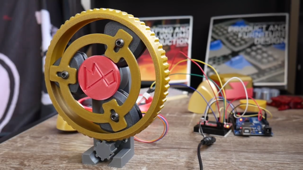
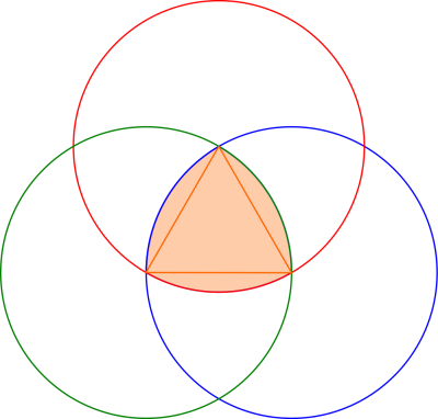
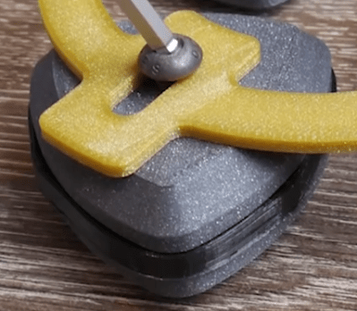
[Angus] finally arrived at a working bearing after a ton of suggestions from the community, and trying a number of attempts until he was able to achieve what he set out to do. The trick was to create a flexible insert (3D printed as well) for the center of the triangle edge, which grips the surfaces the triangle comes into contact with. A frame is also made to hold the bearings in place and allows their centers to move up and down as necessary.

If the thrill seeker within you still isn’t satisfied, maybe you should try the Reuleaux Coaster

Continue reading “The Quest For The Reuleaux Triangle Bearing”

Motor Test Bench Talks The Torque

Salvaging a beefy motor is one life’s greatest pleasures for a hacker, but, when it comes to using it in a new project, the lack of specs and documentation can be frustrating. [The Post Apocalyptic Inventor] has a seemingly endless stockpile of scavenged motors, and decided to do something about the problem.

Once again applying his talent for junk revival, [TPAI] has spent the last year collecting, reverse-engineering and repairing equipment built in the 1970s, to produce a complete electric motor test setup. Parameters such as stall torque, speed under no load, peak power, and more can all easily be found by use of the restored test equipment. Key operating graphs that would normally only be available in a datasheet can also be produced.

The test setup comprises of a number of magnetic particle brakes, combined power supply and control units, a trio of colossal three-phase dummy loads, and a gorgeously vintage power-factor meter.

Motors are coupled via a piece of rubber to a magnetic particle brake. The rubber contains six magnets spaced around its edge, which, combined with a hall sensor,  are used to calculate the motor’s rotational speed. When power is applied to the coil inside the brake, the now magnetised internal powder causes friction between the rotor and the stator, proportional to the current through the coil. In addition to this, the brake can also measure the torque that’s being applied to the motor shaft, which allows the control units to regulate the brake either by speed or torque. An Arduino slurps data from these control units, allowing characteristics to be easily graphed.

If you’re looking for more dynamometer action, last year we featured this neatly designed unit – made by some Cornell students with an impressive level of documentation.

Continue reading “Motor Test Bench Talks The Torque”

Nerf Blaster Goes Next-level With Propane Power

There are no shortage of Nerf gun mods out there. From simply upgrading springs to removing air restrictors, the temptation of one-upping your opponents in a Nerf war speaks to many!

Not content with such lowly modifications [Peter Sripol] decided that his blaster needed to see some propane action.

[Peter] completely stripped out the existing firing mechanism before creating a new combustion chamber from some soldered copper pipe. He added a propane tank and valve on some 3D-printed mounts, and replaced the barrel to produce some intense firepower.

To ignite the fuel inside the combustion chamber, some taser circuitry creates the voltage needed to jump the spark gap inside whilst an added switch behind the trigger kicks off the whole process. After experimenting with different ignition methods, [Peter] eventually found that positioning the spark in the center of the chamber provided the best solution for efficient combustion and non-deafening volume.

Though highly dependant on the amount of gas in the chamber during combustion, the speed of the dart was able to reach a maximum of 220 fps – that’s a whopping 150mph!

Next follows the obligatory sequence for all souped-up Nerf guns:  slow motion annihilation of various food items and beverage containers. To obtain some extra punch, some custom Nerf darts were 3D-printed, including one with a fearsome nail spear-head.

We strongly advise against taking up [Peter] on any offer of Nerf based warfare, but you can check out his insane plane adventures or last winter’s air sled.

Continue reading “Nerf Blaster Goes Next-level With Propane Power”

Laser Projector Ditches Galvanometer For Spinning Drum

Laser projectors like those popular in clubs or laser shows often use mirror galvanometers to reflect the laser and draw in 2D. Without galvos, and on a tight budget, [Vitaliy Mosesov] decided that instead of downgrading the quality, he would seek an entirely different solution: a spinning mirror drum.

He fires a laser at a rotating drum with twelve mirror faces, each at a different adjustable vertical angle. The laser will hit a higher or lower point on the projection surface depending on which mirror it’s reflecting off – this creates resolution in the Y direction.

Timing the pulsing of the laser so that it reflects off the mirror at a certain horizontal angle provides the X resolution.

As you can already tell, speed and timing is critical for this to work. So much so that [Vitaliy] decided he wanted to overclock his Arduino – from 16 MHz to 24.576 MHz. Since this changes the baud rate, an AVR ISP II was used for programming after the modification, and the ‘duino’s hardware serial initialization had to be hacked too.

For the laser itself, [Vitaliy] designed some nifty driver circuitry, which can respond quickly to the required >50 kHz modulation, supply high current, and filter out voltage transients on the power supply (semiconductor lasers have no protection from current spikes).

On the motor side of things, closed loop control is essential. A photo-interrupter was added to the drum for exact speed detection, as well as a differentiator to clean up the signal. Oh, and did we mention the motor is from a floppy disk drive?

We’ve actually seen builds like this before, including a dot-matrix version with multiple lasers and one made apparently out of Meccano and hot-glue that can project a Jolly Wrencher. But this build, with its multiple, adjustable mirrors, is a beauty.  Check it out in action below.

Continue reading “Laser Projector Ditches Galvanometer For Spinning Drum”

Hide Secret Messages In Plain Sight With Zero-Width Characters

Fingerprinting text is really very nifty; the ability to encode hidden data within a string of characters opens up a large number of opportunities. For example, someone within your team is leaking confidential information but you don’t know who. Simply send each team member some classified text with their name encoded in it. Wait for it to be leaked, then extract the name from the text — the classic canary trap.

Here’s a method that hides data in text using zero-width characters. Unlike various other ways of text fingerprinting, zero width characters are not removed if the formatting is stripped, making them nearly impossible to get rid of without re-typing the text or using a special tool. In fact you’ll have a hard time detecting them at all – even terminals and code editors won’t display them.

To make the process easy to perform, [Vedhavyas] created a command line utility to embed and extract a payload using any text. Each letter in the secret message is converted to binary, then encoded in zero-width characters. A zero-width-non-joiner character is used for 0, and a zero-width-space character for 1.

[Vedhavyas’] tool was inspired by a post by [Tom], who uses a javascript example (with online demo) to explain what’s going on. This lets you test out the claim that you can paste the text without losing the hidden data. Try pasting it into a text editor. We were able to copy it again from there and retrieve the data, but it didn’t survive being saved and cat’d to the command line.

Of course, to get your encoding game really tight, you should be looking at getting yourself an enigma wristwatch

Continue reading “Hide Secret Messages In Plain Sight With Zero-Width Characters”

Universal Chip Analyzer: Test Old CPUs In Seconds

Collecting old CPUs and firing them up again is all the rage these days, but how do you know if they will work? For many of these ICs, which ceased production decades ago, sorting the good stuff from the defective and counterfeit is a minefield.

Testing old chips is a challenge in itself. Even if you can find the right motherboard, the slim chances of escaping the effect of time on the components (in particular, capacitor and EEPROM degradation) make a reliable test setup hard to come by.

Enter [Samuel], and the Universal Chip Analyzer (UCA). Using an FPGA to emulate the motherboard, it means the experience of testing an IC takes just a matter of seconds. Why an FPGA? Microcontrollers are simply too slow to get a full speed interface to the CPU, even one from the ’80s.

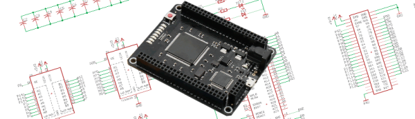
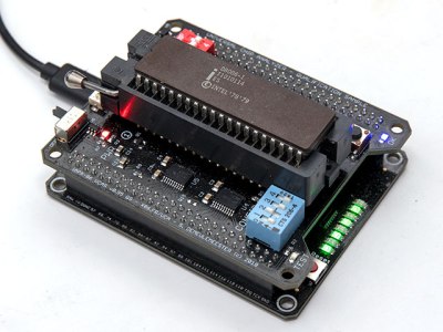
So, how does it actually test? Synthesized inside the FPGA is everything the CPU needs from the motherboard to make it tick, including ROM, RAM, bus controllers, clock generation and interrupt handling. Many testing frequencies are supported (which is helpful for spotting fakes), and if connected to a computer via USB, the UCA can check power consumption, and even benchmark the chip. We can’t begin to detail the amount of thought that’s gone into the design here, from auto-detecting data bus width to the sheer amount of models supported, but you can read more technical details here.

The Mojo v3 FPGA development board was chosen as the heart of the project, featuring an ATmega32U4 and Xilinx Spartan 6 FPGA. The wily among you will have already spotted a problem – the voltage levels used by early CPUs vary greatly (as high as 15V for an Intel 4004). [Samuel]’s ingenious solution to keep the cost down is a shield for each IC family – each with its own voltage converter.

Continue reading “Universal Chip Analyzer: Test Old CPUs In Seconds”