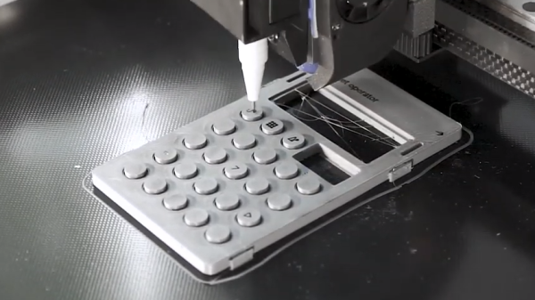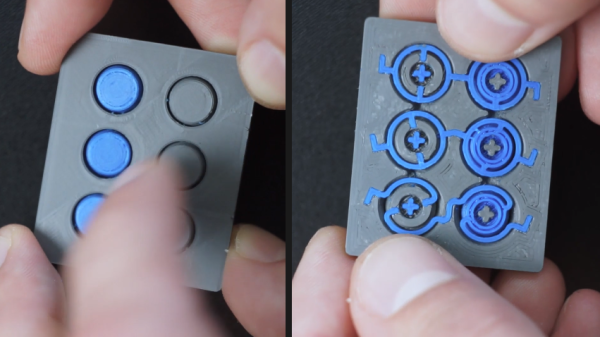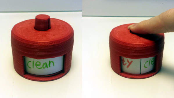
[u407]’s 3D printed Signspinner was created as a clean/dirty indicator for a dishwasher, and at its heart is a mechanism that works a lot like that of a retractable ballpoint pen. Every click of the plunger spins the circular label inside by one-quarter of a rotation. In [u407]’s case it only needs to alternate between showing “clean” and “dirty”, but there are in fact four total label positions.
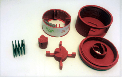 The entire mechanism including the spring is 3D printed, but the spring is PETG and the rest is PLA. [u407] doubts PLA would work for the spring because of how much it gets compressed, but suggests that ABS might work as an alternative.
If you’re having trouble visualizing how this mechanism works, we covered [Bill Hammack] explaining exactly how retractable ballpoint pens work which should make it perfectly clear. It’s fundamentally the same principle.
[via Reddit]
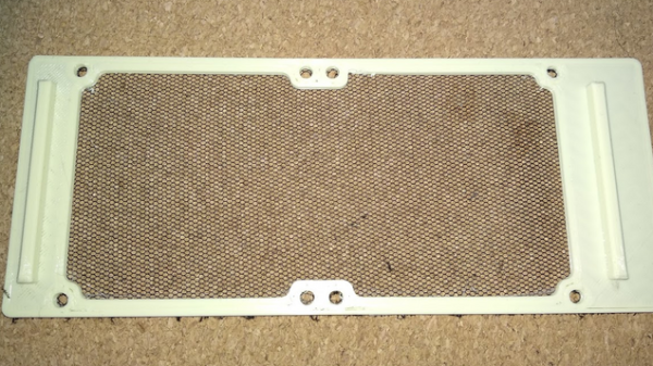
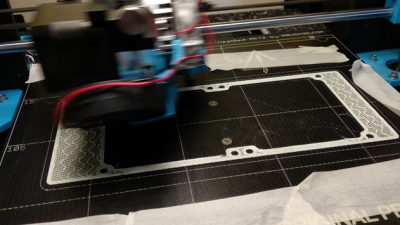 The basic idea is that a 3D print is started, then paused after a few layers. A fine fabric mesh (like tulle, commonly used for bridal veils) is then stretched taut across the print bed, and printing is resumed. If all goes well, the result is 3D printed elements embedded into a flexible, wearable sheet.