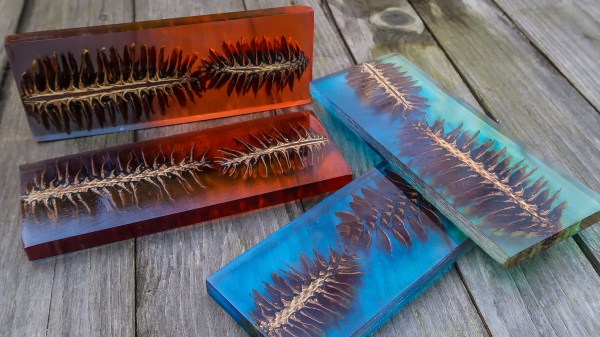
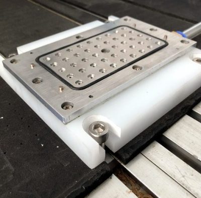
[Black Beard Projects] sealed some pine cones in colored resin, then cut them in half and polished them up. The results look great, but what’s really good about this project is that it clearly demonstrates the necessary steps and techniques from beginning to end. He even employs some homemade equipment, to boot.
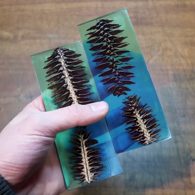 Briefly, the process is to first bake the pine cones to remove any moisture. Then they get coated in a heat-activated resin for stabilizing, which is a process that infuses and pre-seals the pine cones for better casting results. The prepped pine cones go into molds, clear resin is mixed with coloring and poured in. The resin cures inside a pressure chamber, which helps ensure that it gets into every nook and cranny while also causing any small air bubbles introduced during mixing and pouring to shrink so small that they can’t really be seen. After that is cutting, then sanding and polishing. It’s an excellent overview of the entire process.
The video (which is embedded below) also has an outstanding depth of information in the details section. Not only is there an overview of the process and links to related information, but there’s a complete time-coded index to every action taken in the entire video. Now that’s some attention to detail.
Continue reading “How To Make Bisected Pine Cones Look Great, Step-by-Step”
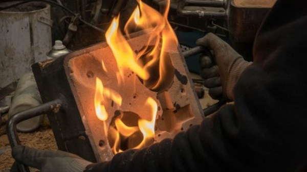
 [critsrandom] shared the method

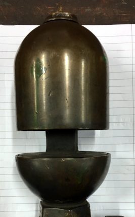 The original whistles are a peek into a different era. The bell type whistle has three major components: a large bell at the top, a cup at the base, and a central column through which steam is piped. These whistles were usually made by apprentices, as they required a range of engineering and manufacturing skills to produce correctly, but were not themselves a critical mechanical component.


