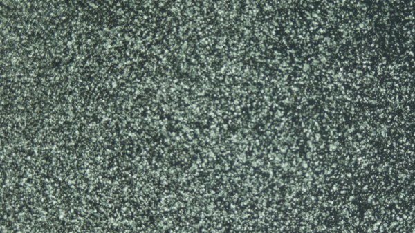
When it comes to 3D scanning, a perfect surface looks a lot like the image above: thousands of distinct and random features, high contrast, no blurry areas, and no shiny spots. While most objects don’t look quite that good, it’s possible to get usable results anyway, and that’s what [Thomas] aims to help people do with his tips on how to create a perfect, accurate 3D scan with photogrammetry.
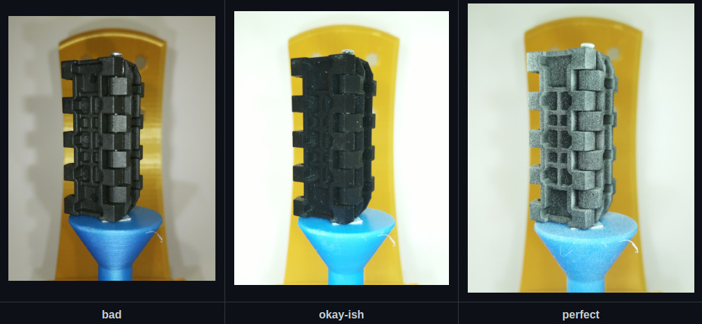
3D scanning in general is pretty far from being as simple as “point box, press button”, but there are tools available to make things easier. Good lighting is critical, polarizers can help, and products like chalk spray can temporarily add matte features to otherwise troublesome, shiny, or featureless objects. [Thomas] provides visuals of each of these, so one can get an idea of exactly what each of those elements brings to the table. There’s even a handy flowchart table to help troubleshoot and improve tricky scan situations.
[Thomas] knows his stuff when it comes to 3D scanning, seeing as he’s behind the OpenScan project. The last time we featured OpenScan was back in 2020, and things have clearly moved forward since then with a new design, the OpenScan Mini. Interesting in an open-sourced scanning solution? Be sure to give it a look.