Bot Makes Etch A Sketch Art In One Continuous Line

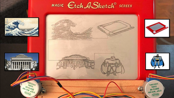
Introduced in 1960 for the princely sum of $2.99 ($25.00 today), Etch A Sketch was to become a standard issue item for the Baby Boomers’ toy box. As enchanting as the toy seems, it’s hard to see why it had staying power: it was hard for young fingers to twirl the knobs, diagonal lines and smooth curves required a concert pianist’s fine motor control, and whatever drawings we managed to make were erased at the slightest jostle of the tablet.

Intent on righting these wrongs, [Sunny Balasubramanian] not only motorized an Etch A Sketch, but he’s also given it a mind of its own in a way. For those unfamiliar with the toy, it’s basically a manual X-Y plotter that drags a stylus across the underside of a glass screen, scraping off a silver powder clinging to the glass to make dark lines. Replacing the knobs with steppers is straightforward, of course, but driving them is the trick. [Sunny] hooked his up to a Raspberry Pi and wrote some Python code to drive them. The Pi also accepts input image files and processes them for rendering through the plotter, first doing Canny edge detection in OpenCV, then plotting a single path through the largest collection of connected pixels in the image. From there it’s just a matter of spinning the motors to create surprisingly detailed images. Check out the short video below to see it in action.

It’s hardly the first automatic Etch A Sketch we’ve seen – here’s one that automates everything including the shake to erase the drawing. That one cheats a little though, in that it rasters across the screen like a CRT. We really like how this one just does a single path. Pretty clever.

Continue reading “Bot Makes Etch A Sketch Art In One Continuous Line”

Epoxy Fix For A Combusted PCB

When the Magic Smoke is released, chances are pretty good that you’ve got some component-level diagnosis to do. It’s usually not that hard to find the faulty part, charred and crusty as it likely appears. In that case, some snips, a new non-crusty part, and a little solder are usually enough to get you back in business.

But what if the smoke came not from a component but from the PCB itself? [Happymacer] chanced upon this sorry situation in a power supply for an electric gate opener. Basking in the Australian sunshine for a few years, the opener started acting fussy at first, then not acting at all. Inspection of its innards revealed that some unlucky ants had shorted across line and neutral on the power supply board, which burned not only the traces but the FR4 of the board as well. Rather than replace the entire board, [Happymacer] carefully removed the carbonized (and therefore conductive) fiberglass and resin, leaving a gaping hole in the board. He fastened a patch for the hole from some epoxy glue; Araldite is the brand he used, but any two-part epoxy, like JB Weld, should work. One side of the hole was covered with tape and the epoxy was smeared into the hole, and after a week of curing and a little cleanup, it was ready for duty. The components were placed into freshly drilled holes, missing traces were replaced with wire, and it seems to be working fine.

This seems like a great tip to keep in mind for when catastrophe strikes your boards. There are more extreme ways to do it, of course, but perhaps none so flexible. After all, epoxy is versatile stuff.

Bask In The Warm Glow Of DIY Incandescent Bulbs

With most of the apparatus and instruments we now take for granted yet to be developed, the early pioneers of the Electric Age had to bring a lot to the lab besides electrical skills. Machining, chemistry, and metallurgy were all basic skills that the inventor either had to have or hire in. Most of these skills still have currency of course, but one that was once crucial – glassblowing – has sadly fallen into relative obscurity.

There are still practitioners of course, like [2SC1815] who is learning how to make homemade incandescent light bulbs. The Instructable is in both English and Japanese, and the process is explained in some detail. Basic supplies include soda-lime glass tubing and pre-coiled tungsten filaments. Support wires are made from Dumet, an alloy of iron, nickel, and cobalt with an oxidized copper cladding which forms a vacuum-tight seal with molten glass. The filament is crimped to the Dumet leads and pinched into a stem of glass tubing. A bulb is blown in another piece of tubing and the two are welded together, evacuated with a vacuum pump, and sealed. The bulbs are baked after sealing to drive off any remaining water vapor. The resulting bulbs have a cheery glow and a rustic look that we really like.

Of course, it’s not a huge leap from DIY light bulbs to making your own vacuum tubes. That’s how [Dalibor Farny] got started on his handmade Nixie business, after all.

Minimal Blinky Project Makes The Chip The Circuit Board

We’ve got a thing for projects that have no real practical value but instead seek to answer a simple yet fundamental question: I wonder if I can do that? This dead-bug style 555 blinky light is one of those projects, undertaken just to see how small a circuit can be. Pretty small, as it turns out, and we bet it can get even smaller.

[Danko]’s minimal circuit is about as small as possible for the DIP version of the venerable 555 chip. The BOM is stripped to the bone: just the chip, three resistors, a capacitor, and an LED. All the discrete components are SMDs in 0805. The chip’s leads are bent around the package to form connections, and the SMDs bridge those “traces” to complete the circuit. [Danko] shows the build in step-by-step detail in the video below. There’s some fairly fine work here, but we can’t help wondering just how far down the scale this could be pushed. We know someone’s made a smaller blinky using a tiny microcontroller, but we’d love to see this tried with the BGA version of the chip which is only 1.4 mm on a side.

Cheers to [Danko] for trying this out and having some fun with an old chip. He seems to have a bit of a thing for the 555; check out this cute robot sculpture that’s built around the chip.

Continue reading “Minimal Blinky Project Makes The Chip The Circuit Board”

Self-Solving Rubik’s Cube

Rubik’s Cube has been around for what seems like forever now, and has spawned an entire subculture devoted to solving the puzzle with automation. Most Rubik robots put the cube in a specially designed cradle bristling with actuators and sensors, and while those rigs are impressive, they don’t come close to this robotic Rubik solver built into the cube itself.

Fair warning that [Human Controller] doesn’t provide much detail on this build other than pictures; even translating the Japanese web page doesn’t offer much more information. But there are pictures, plus the video below, which reveal the engineering masterpiece encased within the standard sized Rubik’s cube. The internal mechanism of the original cube had been replaced by a spherical assembly around which the cube’s faces rotate. The sphere, which appears to be 3D-printed, houses six motors and gear trains, along with a microcontroller board and what appear to be Hall sensor boards to detect the position of each face. Everything is wired up with magnet wire to keep bundles to a minimum size, and buried deep inside is a LiPo battery pack. A disassembly video offers further clues to this ingenious device’s inner workings.

Once the cube senses that it has been scrambled, it sets to work on the solution, walking all over the table in the process. It’s clearly not just recording the scrambling steps and playing them back in reverse; the video below shows far more moves to solve the cube than the 15 it took to scramble it.

While we’re always impressed by marvels of speed like this robot with a 637 millisecond solve time, putting everything needed to solve the cube inside it is a feat worth celebrating. Here’s hoping that a build log shows up soon to satisfy our need for details.

Continue reading “Self-Solving Rubik’s Cube”

Cheating The Perfect Wheelie With Sensors And Servos

Everyone remembers popping their first wheelie on a bike. It’s an exhilarating moment when you figure out just the right mechanics to get balanced over the rear axle for a few glorious seconds of being the coolest kid on the block. Then gravity takes over, and you either learn how to dismount the bike over the rear wheel, or more likely end up looking at the sky wondering how you got on the ground.

Had only this wheelie cheating device been available way back when, many of us could have avoided that ignominious fate. [Tom Stanton]’s quest for the perfect wheelie led him to the design, which is actually pretty simple. The basic idea is to apply the brakes automatically when the bike reaches the critical angle beyond which one dares not go. The brakes slow the bike, the front wheel comes down, and the brakes release to allow you to continue pumping along with the wheelie. The angle is read by an accelerometer hooked to an Arduino, and the rear brake lever is pulled by a hobby servo. We honestly thought the servo would have nowhere near the torque needed, but in fact it did a fine job. As with most of [Tom]’s build his design process had a lot of fits and starts, but that’s all part of the learning. Was it worth it? We’ll let [Tom] discuss that in the video, but suffice it to say that he never hit the pavement in his field testing, although he appeared to be wheelie-proficient going into the project.

Still, it was an interesting build, and begs the question of how the system could be improved. Might there be some clues in this self-balancing motorized unicycle?

Continue reading “Cheating The Perfect Wheelie With Sensors And Servos”

Tearing Into A $1.3 Million Oscilloscope

Most hackers are rankled by those “Warranty Void If Broken” seals on the sides of new test equipment. Even if they’re illegal, they at least put the thought in your head that the space inside your new gear is off-limits, and that prevents you from taking a look at what’s inside. Simply unacceptable.

[Shahriar] has no fear of such labels and tears into just about everything that comes across his bench. Including, most recently, a $1.3 million 110-GHz oscilloscope from Keysight. It’s a teardown that few of us will ever get the chance to do, and fewer still would be brave enough to attempt. Thankfully he does, and the teardown video below shows off the remarkable engineering that went into this monster.

The numbers boggle the mind. Apart from the raw bandwidth, this is a four-channel scope (althought the unit [Shahriar] tested is a two-channel) that doesn’t split its bandwidth across channels. The sampling rate is 256 GS/s and the architecture is 10-bits, so this thing is dealing with 10 terabits per second. We found the extra thick PCBs, which are perhaps 32-layer boards, to be especially interesting, and [Shariar]’s tour of the front end was fascinating.

It all sounds like black magic at first, but he really makes the technology approachable, and his appreciation for fine engineering is obvious. If you’ve got even a passing interest in RF electronics you should check it out. You might want to brush up on microwave topics first, though; this Doppler radar teardown might help.

Continue reading “Tearing Into A $1.3 Million Oscilloscope”