Game And Watch

Give In To Nostalgia With A Retro Game And Watch

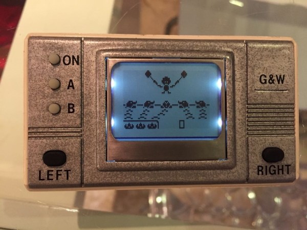
One of the earliest Nintendo products to gain popularity was the Game and Watch product line. Produced by Nintendo between 1980 and 1991, they are a source of nostalgia for many an 80s or 90s kid. These were those electronic handheld games that had pre-drawn monochrome images that would light up to make very basic animations. [Andrew] loved his old “Vermin” game as a kid, but eventually he sold it off. Wanting to re-live those childhood memories, he decided to build his own Game and Watch emulator.

The heart of [Andrew’s] build is a PIC18F4550 USB demo board he found on eBay. The board allows you to upload HEX files directly via USB using some simple front end software. [Andrew] wrote the code for his game in C using MPLAB. His device uses a Nokia 5110 LCD screen and is powered from a small lithium ion battery.

For the housing, [Andrew] started from another old handheld game that was about the right size. He gutted all of the old parts and stuck the new ones in their place. He also gave the housing a sort of brushed metal look using spray paint. The end result is a pretty good approximation of the original thing as evidenced by the video below. Continue reading “Give In To Nostalgia With A Retro Game And Watch”

Remote Tester

A Simple Circuit For Testing Infrared Remote Controls

Every now and then a remote control acts up. Maybe you are trying to change the channel on your television and it’s just not working. A quick way to determine if the remote control is still working is by using a cell phone camera to try to see if the IR LED is still lighting up. That can work sometimes but not always. [Rui] had this problem and he decided to build his own circuit to make it easier to tell if a remote control was having problems.

The circuit uses a Vishay V34836 infrared receiver to pick up the invisible signals that are sent from a remote control. A Microchip 12F683 processes the data and has two main output modes. If the remote control is receiving data continuously, then a green LED lights up to indicate that the remote is functioning properly. If some data is received but not in a continuous stream, then a yellow LED lights up instead. This indicates that the batteries on the remote need to be replaced.

The circuit also includes a red LED as a power indicator as well as RS232 output of the actual received data. The PCB was cut using a milling machine. It’s glued to the top of a dual AAA battery holder, which provides plenty of current to run the circuit.

Philips Lamp Upgrade

Increasing The Brightness Of A Philips LivingColors Lamp

[Martin] recently purchased a Philips LivingColors lamp. It’s a commercial product that basically acts as mood lighting with the ability to change to many different colors. [Martin] was disappointed with the brightness of his off-the-shelf lamp. Rather than spend a few hundred dollars to purchase more lamps, he decided to modify the one he already had.

[Martin] started by removing the front cover of his lamp. He found that there were four bright LEDs inside. Two red, one green, and one blue. [Martin] soldered one wire to the driver of each LED. These wires then connected to four different N-channel MOSFET transistors on a piece of protoboard.

After hooking up his RIGOL oscilloscope, [Martin] was able to see that each LED was driven with a pulse width modulated signal. All he had to do was connect a simple non-addressable RGB LED strip and a power source to his new driver board. Now the lamp can control the LED strip along with the internal LEDs. This greatly extends the brightness of the lamp with minimal modifications to the commercial product. Be sure to check out the video below for a complete walk through. Continue reading “Increasing The Brightness Of A Philips LivingColors Lamp”

Meter Backlight

Adding A Backlight To A Cheap Multimeter

We don’t all need super high quality electronic testing gear. Sometimes second-hand or inexpensive equipment is accurate enough to get the job done. Though it can be a bit annoying to miss out on some of those “luxury” features. [Ekriirke] had this problem with his cheap multimeter. He wished the LCD screen had a backlight for easier visibility, so rather than upgrade to a more expensive unit he just added one himself.

After opening up the multimeter [Ekriirke] found that it ran on a single 12V battery. He realized that the simplest thing to do would be to wire up four white LEDs in series. The four LEDs were arranged within the case off to each side of the LCD, one in each corner. The leads were bent at 90 degree angles and soldered together “dead bug” style. Thin strips of copper foil tape were attached to the PCB in such a way that the anode and cathode from the LEDs would make contact when the case was closed back up.

The tape wraps around to the other side of the PCB where there was more room for the next piece of the circuit. A capacitor, resistor, and transistor are used in conjunction with a momentary switch. This circuit allows [Ekriirke] to turn on the light for about ten seconds by pressing the button one time. The circuit also runs through the meter’s dial switch, preventing the LEDs from being turned on while the meter itself is turned off.

[via Reddit]

Skateboard

On Your Phone While Driving An Electric Skateboard

Skateboards are fun, but you have to do all that pesky kicking in order to get anywhere. That’s why [Nick] decided to build his own electric skateboard. Not only is the skateboard powered with an electric motor, but the whole thing can be controlled from a smart phone.

[Nick] started out with a long board deck that he had made years ago. After cleaning it up and re-finishing it, the board was ready for some wheels. [Nick] used a kit he found online that came with the trucks, wheels, and a belt. The trucks have a motor mount welded in place already. [Nick] used a Turnigy SK3 192KV electric motor to drive the wheels. He also used a Turnigy electronic speed controller to make sure he could vary the speed of the board while riding.

Next [Nick] needed some interface between a smart phone and the motor controller. He chose to use an Arduino Nano hooked up to a Bluetooth module. The Nano was able to directly drive the motor controller, and the Bluetooth module made it easy to sync up to a mobile phone. The Android app was written using MIT’s App Inventor software. It allows for basic control over the motor speed so you can cruise in style. Check out the video below for a slide show and some demonstration clips.

It’s a popular project, and eerily similar to the one we saw a couple months back.

Continue reading “On Your Phone While Driving An Electric Skateboard”

Hard Drive Rootkit Is Frighteningly Persistent

There are a lot of malware programs in the wild today, but luckily we have methods of detecting and removing them. Antivirus is an old standby, and if that fails you can always just reformat the hard drive and wipe it clean. That is unless the malware installs itself in your hard drive firmware. [MalwareTech] has written his own frightening proof of concept malware that does exactly this.

The core firmware rootkit needs to be very small in order to fit in the limited memory space on the hard drive’s memory chips. It’s only a few KB in size, but that doesn’t stop it from packing a punch. The rootkit can intercept any IO to and from the disk or the disk’s firmware. It uses this to its advantage by modifying data being sent back to the host computer. When the computer requests data from a sector on the disk, that data is first loaded into the disk’s cache. The firmware can modify the data sitting in the cache before notifying the host computer that the data is ready. This allows the firmware to trick the host system into executing arbitrary code.

[MalwareTech] uses this ability to load his own custom Windows XP bootkit called TinyXPB. All of this software is small enough to fit on the hard drive’s firmware. This means that traditional antivirus cannot detect its presence. If the owner of the system does get suspicious and completely reformats the hard drive, the malware will remain unharmed. The owner cannot even re-flash the firmware using traditional methods since the rootkit can detect this and save itself. The only way to properly re-flash the firmware would be to use an SPI programmer, which would be too technical for most users.

There are many more features and details to this project. If you are interested in malware, the PDF presentation is certainly worth a read. It goes much more in-depth into how the malware actually works and includes more details about how [MalwareTech] was able to actually reverse engineer the original firmware. If you’re worried about this malicious firmware getting out into the wild, [MalwareTech] assures us that he does not intend to release the actual code to the public.

Beach Sign

LED Sign Brightens Up The Beach After Dark

[Warrior_Rocker’s] family bought a fancy new sign for their beach house. The sign has the word “BEACH” spelled vertically. It originally came with blue LEDs to light up each letter. The problem was that the LEDs had a narrow beam that would blind people on the other side of the room. Also, there was no way to change the color of the LEDs, which would increase the fun factor. That’s why [Warrior] decided to upgrade the sign with multi-colored LEDs.

After removing the cardboard backing of the sign, [Warrior] removed the original LEDs by gently tapping on a stick with a hammer. He decided to use WS2811 LED pixels to replace the original LEDs. These pixel modules support multiple colors and are individually addressable. This would allow for a wide variety of colors and animations. The pixels came covered in a weatherproof resin material. [Warrior] baked the resin with a heat gun until it became brittle. He was then able to remove it entirely using some pliers and a utility knife. Finally, the pixels were held in place with some hot glue.

Rather then build a remote control from scratch, [Warrior] found a compatible RF remote under ten dollars. The LED controller was removed from its housing and soldered to the string of LEDs. It was then hot glued to a piece of cardboard and placed into the sign’s original battery compartment. Check out the video below for a demonstration. Continue reading “LED Sign Brightens Up The Beach After Dark”