SNES Controller Has A Pi Zero In The Trunk

We’re no stranger to seeing people jam a Raspberry Pi into an old gaming console to turn it into a RetroPie system. Frankly, at this point it seems like we’ve got to be getting close to seeing all possible permutations of the concept. According to the bingo card we keep here at Hackaday HQ we’re just waiting for somebody to put one into an Apple Bandai Pippin, creating the PiPi and achieving singularity. Get it done, people.

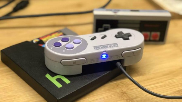
That being said, we’re still occasionally surprised by what people come up with. The Super GamePad Zero by [Zach Levine] is a fairly compelling take on the Pi-in-the-controller theme that we haven’t seen before, adding a 3D printed “caboose” to the stock Super Nintendo controller. The printed case extension, designed by Thingiverse user [Sigismond0], makes the controller about twice as thick, but that’s still not bad compared to modern game controllers.

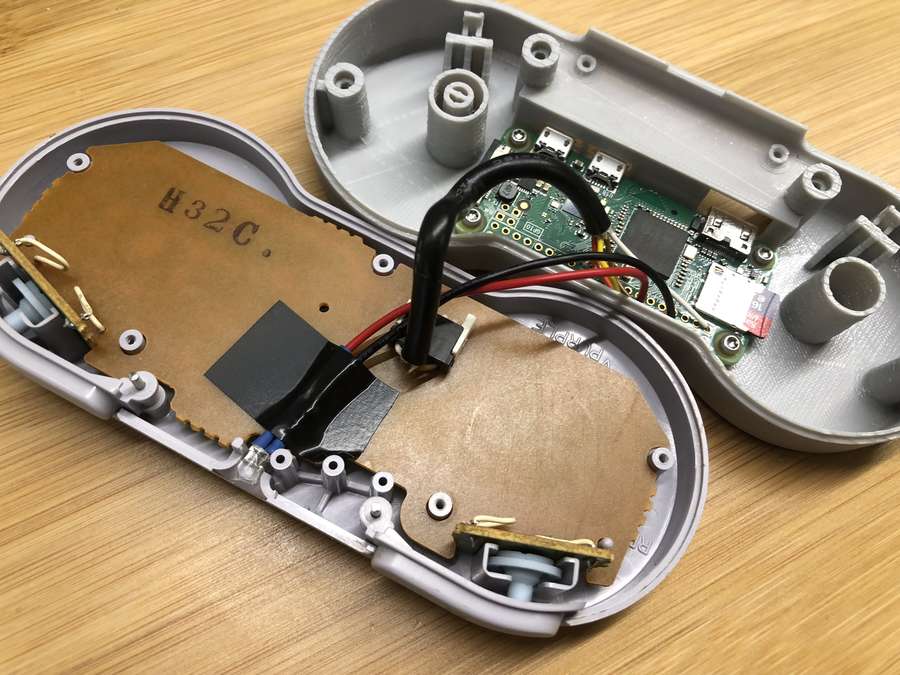
In his guide [Zach] walks the reader through installing the Raspberry Pi running RetroPie in the expanded case. This includes putting a power LED where the controller’s cable used to go, and connecting the stock controller PCB to the Pi’s GPIO pins. This is an especially nice touch that not only saves you time and effort, but retains the original feel of the D-Pad and buttons. Just make sure the buttons on your donor controller aren’t shot before you start the build.

Adding a little more breathing room for your wiring isn’t the only reason to use the 3D printed bottom, either. It implements a very clever “shelf” design that exposes the Pi’s USB and HDMI ports on the rear of the controller. This allows you to easily connect power and video to the device without spoiling the overall look. With integrated labels for the connectors and a suitably matching filament color, the overall effect really does look like it could be a commercial product.

The SNES controller is an especially popular target for hacks and modifications. From commercially available kits to the wide array of homebrew builds, it there’s plenty of people who want to keep this legendary piece of gaming gear going strong into the 21st century

Continue reading “SNES Controller Has A Pi Zero In The Trunk”

A Sneak Peek At Anechoic Chamber Testing

[Mathieu Stephan] has something new in the works, and while he isn’t ready to take the wraps off of it yet, he was kind enough to document his experience putting the mysterious new gadget through its paces inside an anechoic chamber. Considering the majority of us will never get inside of one of these rooms, much less have the opportunity to test our own hardware in one, he figured it was the least he could do.

If you’re not familiar with an anechoic chamber, don’t feel bad. It’s not exactly the sort of thing you’ll have at the local makerspace. Put simply it’s a room designed to not only to remove echos on the inside, but also be completely isolated from the outside. But we aren’t just talking about sound deadening, the principle can also be adapted to work for electromagnetic waves. So not only is in the inside of the anechoic chamber audibly silent, it can also be radio silent.

This is important if you want to test the performance of things like antennas, as it allows you to remove outside interference. As [Mathieu] explains, both the receiver and transmitter can be placed in the chamber and connected to a vector network analyzer (VNA). The device is able to quantify how much energy is being transferred between the two devices, but the results will only be accurate if that’s the only thing the VNA sees on its input port.

[Mathieu] can’t reveal images of the hardware or the results of the analysis because that would give too much away at this point, but he does provide the cleverly edited video after the break as well as some generic information on antenna analysis and the type of results one receives from this sort of testing. Our very own [Jenny List] has a bit more information on the subject if you’d like to continue to live vicariously through the accounts of others. For the rest of us, we’ll just have to settle for some chicken wire and a wooden crate.

Continue reading “A Sneak Peek At Anechoic Chamber Testing”

Rock Out To The Written Word With BookSound

With his latest project, [Roni Bandini] has simultaneously given the world a new type of audiobook and music. Traditional audiobooks are basically the adult equivalent of having somebody read you a bedtime story, but BookSound actually turns the written word into electronic music. You won’t be able to boast to your friends that as a matter of fact, you have read that popular new novel, but at least you might be able to dance to it.

[Roni] says he’s still working on perfecting the word to music mapping, so the results shown in the video after the break are still a bit rough. But even in these early stages there’s no denying this is an exceptionally unique project, and we’re excited to see where it goes from here.

Inside the classy looking 3D printed enclosure is a Raspberry Pi, an OLED display, and the button and switch which make up the extent of the device’s controls. At the end of the arm is a standard Raspberry Pi Camera module, which gives the BookSound a bird’s eye view of the book to be songified.

To turn your favorite book into electronic beats, simply open it up, put it under the gaze of BookSound, and press the button on the front. Because the Raspberry Pi isn’t exactly a powerhouse, it takes about two minutes for it to scan the page, perform optical character recognition (OCR), and compose the track before you start to hear anything.

If you’re wondering what the secret sauce is to turn words into music, [Roni] isn’t ready to share his source code just yet. But he was able to give us a few high-level explanations of what’s going on inside BookSound. For example, to generate the song’s BPM, the software will count how many words per paragraph are on the page: so a book with shorter paragraphs will consequently have a faster tempo to match the speed at which the author is moving through ideas. Similarly, drum kicks are generated based on the number of syllables in each paragraph. In the future, he’s looking at adding “lyrics” by running commonly used words on the page through a text to speech engine and inserting them into the beat.

We’ve seen practical applications of OCR on the Raspberry Pi in the past and even similar looking book scanning arrangements. But nothing quite like BookSound before, which at this point, is really saying something.

Continue reading “Rock Out To The Written Word With BookSound”

3D Print Springs With Hacked GCode

If you’ve used a desktop 3D printer in the past, you’re almost certainly done battle with “strings”. These are the wispy bits of filament that harden in the air, usually as the printer’s nozzle moves quickly between points in open air. Depending on the severity and the material you’re printing with, these stringy interlopers can range from being an unsightly annoyance to triggering a heartbreaking failed print. But where most see an annoying reality of pushing melted plastic around, [Adam Kumpf] of Makefast Workshop sees inspiration.

Noticing that the nozzle of their printer left strings behind, [Adam] wondered if it would be possible to induce these mid-air printing artifacts on demand. Even better, would it be possible to tame them into producing a useful object? As it turns out it is, and now we’ve got the web-based tool to prove it.

As [Adam] explains, you can’t just load up a 3D model of a spring in your normal slicer and expect your printer to churn out a useful object. The software will, as it’s designed to do, recognize the object can’t be printed without extensive support material. Now you could in theory go ahead and print such a spring, but good luck getting the support material out.

The trick is to throw away the traditional slicer entirely, as the layer-by-layer approach simply won’t work here. By manually creating GCode using carefully tuned parameters, [Adam] found it was possible to get the printer to extrude plastic at the precise rate at which the part cooling fan would instantly solidify it. Then it was just a matter of taking that concept and applying it to a slow spiral motion. The end result are functional, albeit not very strong, helical compression springs.

But you don’t have to take their word for it. This research has lead to the creation of an online tool that allows you to plug in the variables for your desired spring (pitch, radius, revolutions, etc), as well as details about your printer such as nozzle diameter and temperature. The result is a custom GCode that (hopefully) will produce the desired spring when loaded up on your printer. We’d love to hear if any readers manage to replicate the effect on their own printers, but we should mention fiddling with your printer’s GCode directly isn’t without its risks: from skipping steps to stripped filament to head crashes.

The results remind us somewhat of the 3D lattice printer we featured a couple of years back, but even that machine didn’t use standard FDM technology. It will be interesting to see what other applications could be found for this particular technique.

Continue reading “3D Print Springs With Hacked GCode”

Mastering OpenSCAD Workflow

As you may have noticed in our coverage, we’re big fans of OpenSCAD around these parts. The fact that several of the Hackaday writers organically found and started using the parametric CAD package on their own is not only a testament to our carefully cultivated hive mind but also to the type of people it appeals to. Hackers love it because it allows you to model physical objects as if you were writing software: models are expressed in code, and its plain text source files can be managed with tools like git and make. If you’re a real Pinball Wizard you could design objects and export them to STL without ever using a graphical interface.

But as you might expect, with such power comes a considerable learning curve. OpenSCAD devotee [Uri Shaked] recently wrote in to share with us his workflow for designing complex interacting mechanisms, which serves as an excellent primer to the world of parametric design. From animating your models to recreating the “vitamins” of your build, his post contains plenty of tips that can help both new and veteran OpenSCAD users alike.

Perhaps the biggest takeaway from his post is that you should be thinking of your projects as a whole, rather than as individual models. [Uri] recalls his early attempts at designing mechanisms: designing each component individually, printing it out, and only then finding out if it fits together with the other pieces. This method of trial and error is probably familiar to anyone who’s designed their own 3D printed parts — but it’s slow and wastes materials. The alternative, as he explains it, is to design all of the pieces at the same time and “assemble” them virtually. This will allow you to check clearances and fitment without dedicating the time and materials to test it in the real world.

In fact, as [Uri] explains, you’re better off spending your time bringing real-world parts into OpenSCAD. By carefully measuring the hardware components you want to interact with (servos, gears, switches, etc), you can create facsimiles of them to use as a reference in your OpenSCAD project. As time goes on, you can build up your own library of drop-in reference models which will accelerate future designs.

He also spends a little time talking about something that doesn’t seem to be terribly well known even among the OpenSCAD converts: you don’t have to use the built-in editor if you don’t want to. Since OpenSCAD source code files are plain text, you can write them in whatever editor you like. The OpenSCAD model viewer even has an option specifically for this scenario, which will cause it to update the rendered preview as soon as it detects the source has been updated. For [Uri] this means he can create his designs in Visual Studio Code with a constantly updating preview in another window.

If you’re looking for examples of what the parametric capabilities of OpenSCAD can do for you, we’ve got no shortage of excellent examples. From creating customized computer cases to saving time by using mathematically derived components. Our very own [Elliot Williams] even has a write up about that most glorious of OpenSCAD commands: hull().

ESP8266 Wi-Fi Instant Camera Is A Simple Shooter

If a camera that combines the immediate gratification of a Polaroid with cloud hosting sounds like something that tickles your fancy, look no farther than this ESP-powered point and shoot camera created by [Martin Fasani]. There’s no screen or complicated configuration on this camera; just press the button and the raw picture pops up on the online gallery. Somehow it’s simultaneously one of the most simplistic and complex implementations of the classic “instant camera” concept, and we love it.

The electronics in the camera itself, which [Martin] calls the FS2, is quite simple. At the core, it’s nothing more than the ESP board, an ArduCAM camera module, and a momentary button for the shutter. To make it portable he added a 2000 mAh Li-ion battery and an Adafruit Micro Micro USB charger. [Martin] added support for an optional 128×64 OLED display for user feedback. Everything is housed in a relatively spacious 3D printed enclosure, leaving some room for possible future hardware.

There are firmware versions for both the ESP8266 and ESP32, so fans of either generation of the popular microcontroller are invited to the party. Processing images is obviously a bit faster if you go with the more powerful 32-bit chip, but on the flip side the ESP8266 uses 3MB of SPI flash as a local buffer for the images during upload, which helps prevent lost images if there’s a problem pushing them to the cloud. The camera is intended to be as simple as possible so right now the only option other than taking still images is a time-lapse mode. [Martin] hopes to implement some additional filters and effects in the future. He’s also hoping others might lend a hand with his firmware. He’s specifically looking for assistance getting autofocus working and implementing more robust error correction for image uploads.

We’ve seen some impressive DIY camera builds using everything from a salvaged thermal sensor to film and molten aluminum. But the quaint simplicity of what [Martin] has put together here really puts his project in a whole new category.

Continue reading “ESP8266 Wi-Fi Instant Camera Is A Simple Shooter”

The How And Why Of Laser Cutter Aiming

Laser aficionado [Martin Raynsford] has built up experience with various laser cutters over the years and felt he should write up a blog post detailing his first-hand findings with an often overlooked aspect of the machines: aiming them. Cheap diode laser cutters and engravers operate in the visible part of the spectrum, but when you get into more powerful carbon dioxide lasers such as the one used in the popular K40 machines, the infrared beam is invisible to the naked eye. A secondary low-power laser helps to visualize the main laser’s alignment without actually cutting the target. There are a couple of ways to install an aiming system like this, but which way works better?

[Martin] explains that there are basically two schools of thought: a head-mounted laser, or a beam combiner. In both cases, a small red diode laser (the kind used in laser pointers) is used to indicate where the primary laser will hit. This allows the user to see exactly what the laser cutter will do when activated, critically important if you’re doing something like engraving a device and only have one chance to get it right. Running a “simulation” with the red laser removes any doubt before firing up the primary laser.

That’s the idea, anyway. In his experience, both methods have their issues. Head-mounted lasers are easier to install and maintain, but their accuracy changes with movement of the machine’s Z-axis: as the head goes up and down, the red laser dot moves horizontally and quickly comes out of alignment. Using the beam combiner method should, in theory, be more accurate, but [Martin] notes he’s had quite a bit of trouble getting both the red and IR lasers to follow the same course through the machine’s mirrors. Not only is it tricky to adjust, but it’s also much more complex to implement and may even rob the laser of power due to the additional optics involved.

In the end, [Martin] doesn’t think there is really a clear winner. Neither method gives 100% accurate results, and both are finicky, though in different scenarios. He suggests you just use whatever method your laser cutter comes with from the factory, as trying to change it probably isn’t worth the effort. But if your machine doesn’t have anything currently, the head-mounted laser is certainly the easier one to retrofit.

In the past, we’ve covered a third and slightly unconventional way of aiming the K40, as well as a general primer for anyone looking to pick up eBay’s favorite laser cutter.