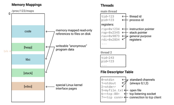
A Honeycomb Patching Robot Powered By Arduino

No, it’s not the kind of honeycomb you’re probably thinking of. We’re talking about the lightweight panels commonly used in aerospace applications. Apparently they’re rather prone to dents and other damage during handling, so Boeing teamed up with students from the California State University to come up with a way to automate the time-consuming repair process.

The resulting machine, which you can see in action after the break, is a phenomenal piece of engineering. But more than that, it’s an impressive use of off-the-shelf components. The only thing more fascinating than seeing this robotic machine perform its artful repairs is counting how many of its core components you’ve got laying around the shop.

Built from aluminum extrusion, powered by an Arduino Due, and spinning a Dewalt cut-off tool that looks like it was just picked it up from Home Depot, you could easily source most of the hardware yourself. Assuming you needed to automatically repair aerospace-grade honeycomb panels, anyway.

At the heart of this project is a rotating “turret” that holds all the tools required for the repair. After the turret is homed and the condition of all the cutting tools is verified, a hole is drilled into the top of the damaged cell. A small tool is then carefully angled into the hole (a little trick that is mechanical poetry in motion) to deburr the hole, and a vacuum is used to suck out any of the filings created by the previous operations. Finally a nozzle is moved into position and the void is filled with expanding foam.

Boeing says it takes up to four hours for a human to perform this same repair. Frankly, that seems a little crazy to us. But then again if we were the ones tasked with repairing a structural panel for a communications satellite or aircraft worth hundreds of millions of dollars, we’d probably take our time too. The video is obviously sped up so it’s hard to say exactly how long this automated process takes, but it doesn’t seem like it could be much more than a few minutes from start to finish.

Continue reading “A Honeycomb Patching Robot Powered By Arduino”

Evolution Of A Backpack VR System

Persistence is what a hacker needs to make it to their goal. That’s exactly what it took for [Erik] to make an untethered VR backpack system.

Starting way back in the Spring of 2019, [Erik] began working on an untethered VR system. Sure, the Oculus Quest was coming out, but it wouldn’t be compatible with the game library of PC based systems. [Erik] decided he wanted the best of both worlds, so he decided to build a backpack that carries a computer powerful enough to drive the Rift S.

The initial system was to use a cut-up backpack, an HP mini PC with an external Nvidia 1060 GPU, and a basic DC-DC converter. The result? Just about nothing worked. The HP’s boot process didn’t play well with an external GPU.

[Erik] went through several iterations of this project. He switched over to a standard PC motherboard and tried a few different DC-DC converters. He settled on a device from HDPLEX rated at 200 watts continuous. The converter plugs directly into a standard 24-pin ATX motherboard power connector and isn’t much larger than the connector itself.

The old backpack with its added padding and wood frame gave way to a Zotac VR go backpack. Only the straps and frame of the Zotac are used, with [Erik’s] custom parts mounted using plywood and 3D printed parts. The outer frame is aluminum, with acrylic panels.

Power comes from 7000 mAH LiFe batteries, with each pack providing an hour of runtime. The Backpack can hold two packs though, so wiring them up in parallel should double that runtime.

We have to say this is an extremely well-documented build. [Erik] explains how he chose each component and the advantages (and pitfalls) of the choices he made. An example would be the RAM he picked. He chose DDR4 with a higher spec than he needed, just so he could undervolt the parts for longer run-times.

Not everything in VR is fun and games though – you can ditch that monitor and go with a VR desktop.

Esper Makes Virtual Reality From Live Reality

There’s a scene in Bladerunner where Deckard puts a photograph in a magical machine that lets him zoom and enhance without limit, and even see around obstacles. In today’s climate, this is starting to seem more plausible, what with all the cameras everywhere. [Jasper van Loenen] explores this concept in Esper, a technological art installation he created in Seoul, Korea during an artist residency.

Esper is a two-part piece that turns virtual reality on its head by showing actual reality in VR. It covers two adjoining rooms, one to record reality, and the other for real-time virtual viewing on headsets. The first is outfitted with 60 ESP32 cameras on custom mounts, all pointing in different directions from various perches and ceiling drops. [Jasper] used an Android app based on openFrameworks to map the cameras’ locations in 3D space. The room next door is so empty, it’s even devoid of FOMO. You don’t want to miss this one, so check it out after the break.

Recreating sci-fi props is all fun and games until the dystopia arrives. Then again, the fact that we can all easily access 70,000 or so insecure surveillance cameras is a pretty good start.

Continue reading “Esper Makes Virtual Reality From Live Reality”

Arduino Drives Astronomy Dome

The South Florida Science Center recently added a new ten-inch telescope and turned to [Andres Paris] and his brother to replace the hand-cranked dome door system. They turned to an Arduino along with some beefy motor drivers. You can see some videos of the beast in operation, below.

According to a Reddit post, the brothers picked up a 5A 12V motor but decided to overdesign and selected an H-bridge that would handle 20A peak current. An IR remote allows the operator to open and shut the door and reed switches sense the extremes of the door’s motion.

Continue reading “Arduino Drives Astronomy Dome”

Multi-Band Receiver On A Chip Controlled By Arduino

The Silicon Labs Si4735 is a single-chip solution for receiving AM, FM, and shortwave radio. With a bit of hacking, it even supports single sideband (SSB). All you’ve got to do is provide it with a suitable control interface, which [Ricardo Lima Caratti] has done with his recent project.

Using an Arduino Pro Mini, a handful of buttons, and a standard TFT display, [Ricardo] has put together a serviceable little receiver with a fairly impressive user interface. We especially like the horizontal bars indicating the signal to noise ratio and received signal strength. The next evolution would be to put this whole rig into some kind of enclosure, but for now he seems content to control the action with a handful of unlabeled buttons on a piece of perfboard.

Of course, the presentation of this receiver isn’t really the point; it’s more of a proof of concept. You see, [Ricardo] is the person who’s actually developed the library that allows you to control the Si4735 from your microcontroller of choice over I2C. He’s currently tested it with several members of the official (and not so official) Arduino family, as well as the ESP32.

The documentation [Ricardo] has put together for his MIT licensed Arduino Si4735 library is nothing short of phenomenal. Seriously, if all open source projects were documented even half as well as this one is, we’d all be a few notches closer to world peace. Even if you aren’t terribly interested in adding shortwave radio reception to your next project, you’ve got to browse his documentation just to see where the high water mark is.

We actually first heard about this library a few days ago when we covered another receiver using the Si4735 and [Ricardo] popped into the comments to share some of the work he’d been doing to push the state-of-the-art forward for this promising chip.

Continue reading “Multi-Band Receiver On A Chip Controlled By Arduino”

This DIY Dynamometer Shows Just What A Motor Can Do

Back in high school, all the serious gearheads used to brag about two things: their drag strip tickets, and their dynamometer reports. The former showed how fast their muscle car could cover a quarter-mile, while the latter was documentation on how much power their carefully crafted machine could deliver. What can I say; gas was cheap and we didn’t have the Internet to distract us.

Bragging rights are not exactly what [Jeremy Fielding] has in mind for his DIY dynamometer, nor is getting the particulars on a big Detroit V8 engine. Rather, he wants to characterize small- to medium-sized electric motors, with an eye toward repurposing them for different projects. To do this, he built a simple jig to measure the two parameters needed to calculate the power output of a motor: speed and torque. A magnetic tachometer does the job of measuring the motor’s speed, but torque proved a bit more challenging. The motor under test is coupled to a separate electric braking motor, which spins free when it’s not powered. A lever arm of known length connects to the braking motor on one end while bearing on a digital scale on the other. With the motor under test spun up, the braking motor is gradually powered, which rotates its housing and produces a force on the scale through the lever arm. A little math is all it takes for the mystery motor to reveal its secrets.

[Jeremy]’s videos are always instructional, and the joy he obviously feels at discovery is infectious, so we’re surprised to see that we haven’t featured any of his stuff before. We’ve seen our share of dynos before, though, from the tiny to the computerized to the kind that sometimes blows up.

Continue reading “This DIY Dynamometer Shows Just What A Motor Can Do”

Scott Shawcroft Is Programming Game Boys With CircuitPython

Some people like to do things the hard way. Maybe they drive a manual transmission, or they bust out the wire wrap tool instead of a soldering iron, or they code in assembly to stay close to the machine. Doing things the hard way certainly has its merits, and we are not here to argue about that. Scott Shawcroft — project lead for CircuitPython — on the other hand, makes a great case for doing things the easy way in his talk at the 2019 Hackaday Superconference.

In fact, he proved how easy it is right off the bat. There he stood at the podium, presenting in front of a room full of people, poised at an unfamiliar laptop with only the stock text editor. Yet with a single keystroke and a file save operation, Scott was able make the LEDs on his Adafruit Edge Badge — one of the other pieces of hackable hardware in the Supercon swag bag — go from off to battery-draining bright.

Code + Community

As Scott explains, CircuitPython prides itself on being equal parts code and community. In other words, it’s friendly and inviting all the way around. Developing in CircuitPython is easy because the entire environment — the code, toolchain, and the devices — are all extremely portable. Interacting with sensors and other doodads is easy because of the import and library mechanics Python is known for, both of which are growing within the CircuitPython ecosystem all the time.

CircuitPython is so friendly that it can even talk to old hardware relatively easily without devolving into a generational battle. To demonstrate this point, Scott whipped out an original Nintendo Game Boy and a custom cartridge, which he can use to play fun sounds via the Game Boy’s CPU.

Now You’re Playing With Python

It’s interesting to see the platforms on which Scott has used the power of CircuitPython. The Game Boy brings the hardware for sound and pixel generation along with some logic, but he says it’s the code on the cartridge that does the interesting stuff.

The CPU communicates with carts at a rate of 1MHz. As long as you can keep this rate up and the CPU understands your instructions, you can get it to do anything you want.

Scott’s custom cart has a 120MHz SAMD51. He spends a second explaining how he gets from Python libraries down to the wire that goes to the Game Boy’s brain — basically, the C code underneath CircuitPython accesses direct structs defined within the SAMD to do Direct Memory Access (DMA), which allows for jitter-free communication at 1MHz.

He’s using the chip’s lookup tables to generate a 1MHz signal out of clock, read, and A15 in order to send music-playing instructions to the sound register of the Game Boy’s CPU. It sounds like a lot of work, but CircuitPython helps to smooth over the dirty details, leaving behind a simpler interface.

If you want easy access to hardware no matter how new or nostalgic, the message is clear: snake your way in there with CircuitPython.

Continue reading “Scott Shawcroft Is Programming Game Boys With CircuitPython”