A Few Of Our Favorite Chips: 4051 Analog Mux

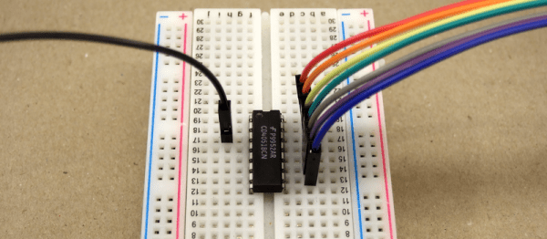
Raindrops on roses, and whiskers on kittens? They’re alright, I suppose. But when it comes down to it, I’d probably rather have a bunch of 4051, 4052, and 4053 analog multiplexers on the component shelf. Why? Because the ability to switch analog signals around, routing them at will, under control of a microcontroller is tremendously powerful.

Whether you want to read a capacitive-sensing keyboard or just switch among audio signals, nothing beats a mux! Read on and see if you agree.

Continue reading “A Few Of Our Favorite Chips: 4051 Analog Mux”

If The I And Q Of Software Defined Radio Are Your Nemesis, Read On

For those of us whose interests lie in radio, encountering our first software defined radio must have universally seemed like a miracle. Here is a surprisingly simple device, essentially a clever mixer and a set of analogue-to-digital or digital-to-analogue converters, that can import all the complex and tricky-to-set-up parts of a traditional radio to a computer, in which all signal procession can be done using software.

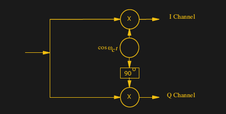
A quadrature mixer. Jugandi (Public domain).

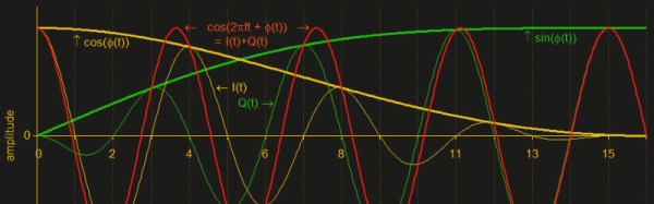
When your curiosity gets the better of you and you start to peer into the workings of a software defined radio though, you encounter something you won’t have seen before in a traditional radio. There are two mixers fed by a two local oscillators on the same frequency but with a 90 degree phase shift, and in a receiver the resulting mixer products are fed into two separate ADCs. You encounter the letters I and Q in relation to these two signal paths, and wonder what on earth all that means.

Continue reading “If The I And Q Of Software Defined Radio Are Your Nemesis, Read On”

Hackaday Links: May 14, 2017

Maker Faire Bay Area is next weekend, and you know what that means: we’re having a meetup on Saturday night. If you’re in the area, it’s highly recommended you attend. It’s a blinky bring-a-hack with booze. You can’t beat it. I heard the OPShark is showing up. All hail the OPShark. You’re gonna want to RSVP if you’re going k thx.

It only took twelve years, but [ladyada] finally got herself on the cover of Make.

Nvidia has the Jetson, an extremely powerful single board computer + GPU meant for machine learning, imagifying, and robotics applications. If you want to do fancy ML stuff with low power devices, I’d highly recommend you check the Jetson out. Of course, the Jetson is only the brains of any Machine Learning robot; you also need some muscle. To that end, Nvidia released the Isaac robotic simulator. It’s a simulator for standard bits of hardware like quadcopters, hovercrafts (?), robotic arms, and yes, selfie drones. What does this mean? Standardized hardware means someone is going to produce 3rd party hardware, and that’s awesome.

This is just an observation, but fidget spinners are just now hitting the mainstream. We didn’t know what they were for a year ago, and we don’t know now.

A Hebocon is a shitty robot battle. DorkbotPDX just had their first Hebocon and the results were… just about as shitty as you would expect. Since this is a shitty robot battle, a MakerBot made an appearance. This robot, SpitterBot, was designed to blow extruded filament all over its opponent. Did the MakerBot win? Yes, SpitterBot won the ‘Poorest Quality’ award.

Supplyframe, Hackaday’s parent company, hosts monthly-ish electronic get-togethers in the San Fransisco office. The focus of these meetups is to find someone cool who built something awesome and get them to talk about it. The March meetup featured [Pete Bevelacqua] who built a Vector Network Analyzer from scratch. The video is worth a watch.

Simulating The Learn-by-Fixing CPU

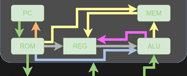
Last time I looked at a simple 16-bit RISC processor aimed at students. It needed a little help on documentation and had a missing file, but I managed to get it to simulate using a free online tool called EDA Playground. This time, I’ll take you through the code details and how to run the simulation.

You’ll want to refer to the previous post if you didn’t read it already. The diagrams and tables give a high-level overview that will help you understand the files discussed in this post.

If you wanted to actually program this on a real FPGA, you’d have a little work to do. The memory and register initialization is done in a way that works fine for simulation, but wouldn’t work on a real FPGA. Anyway, let’s get started!

Continue reading “Simulating The Learn-by-Fixing CPU”

Designing For Fab: A Heads-Up Before Designing PCBs For Professional Assembly

Designing pcbs for assembly is easy, right? We just squirt all the footprints onto a board layout, connect all the traces, send out the gerbers and position files, and we’re done–right?

Whoa, hold the phone, there, young rogue! Just like we can hack together some working source code with variables named after our best friends, we can also design our PCBs in ways that make it fairly difficult to assemble.

However, by following the agreed-upon design specs, we’ll put ourselves on track for success with automated assembly. If we want another party to put components on our boards, we need to clearly communicate the needed steps to get there. The best way to do so is by following the standards.

Proper Footprint Orientation

Now, for a momImage Credit: https://encrypted-tbn2.gstatic.com/images?q=tbn:ANd9GcQBEztpnSxpN_IRjq3y8GbetrMHKuoSu_s6myiFOHilL2FlQKyLrgent, let’s imagine ourselves as the tip of a vacuum pickup tool on a pick-and-place machine. These tools are designed to pick up components on the reel from their centroid and plunk them on their corresponding land pattern. Seems pretty straightforward, right? It is, provided that we design our footprints knowing that they’ll one day come face-to-face with the pick-and-place machine.
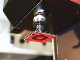
To get from the reel to the board, we, the designers, need two bits of information from out part’s datasheet: the part centroid and the reel orientation.

The part centroid is an X-Y location that calls out the center-of-mass of the part. It basically tells the machine: “pick me up from here!” As designers, it’s our responsibility to design all of our footprints such that the footprint origin is set at the part’s centroid. If we forget to do so, the pick-and-place will try to suck up our parts from a location that may not stick very well to the package, such as: the corner.

Continue reading “Designing For Fab: A Heads-Up Before Designing PCBs For Professional Assembly”

Friday Hack Chat: Tenaya Hurst From Arduino

Join us this Friday at noon PDT for a Hack Chat with Tenaya Hurst of Arduino. If you’ve been one of the big Maker Faires over the last few years (or innumerable other live events) and stopped by the Arduino area you’ve probably met Tenaya. She is the Education Accounts Manager for Arduino and loves working with wearable electronics.

Come and discuss maker education and the role Arduino is playing in getting our students excited about electronics, and STEAM education in general. Tenaya will also be discussing a new wearable tech kit she’s been working on. We hope to see the gear in person at Bay Area Maker Faire next week.

Here’s How To Take Part:

join-hack-chatOur Hack Chats are live community events on the Hackaday.io Hack Chat group messaging.

Log into Hackaday.io, visit that page, and look for the ‘Join this Project’ Button. Once you’re part of the project, the button will change to ‘Team Messaging’, which takes you directly to the Hack Chat.

You don’t have to wait until Friday; join whenever you want and you can see what the community is talking about.

OBDII to Speed Pulse: Atmel ICE

Building An OBD Speed Pulse: Behold The ICE

I am a crappy software coder when it comes down to it. I didn’t pay attention when everything went object oriented and my roots were always assembly language and Real Time Operating Systems (RTOS) anyways.

So it only natural that I would reach for a true In-Circuit-Emulator (ICE) to finish of my little OBDII bus to speed pulse generator widget. ICE is a hardware device used to debug embedded systems. It communicates with the microcontroller on your board, allowing you to view what is going on by pausing execution and inspecting or changing values in the hardware registers. If you want to be great at embedded development you need to be great at using in-circuit emulation.

Not only do I get to watch my mistakes in near real time, I get to make a video about it.

Getting Data Out of a Vehicle

I’ve been working on a small board which will plug into my car and give direct access to speed reported on the Controller Area Network (CAN bus).

To back up a bit, my last video post was about my inane desire to make a small assembly that could plug into the OBDII port on my truck and create a series of pulses representing the speed of the vehicle for my GPS to function much more accurately. While there was a wire buried deep in the multiple bundles of wires connected to the vehicle’s Engine Control Module, I have decided for numerous reasons to create my own signal source.

At the heart of my project is the need to convert the OBDII port and the underlying CAN protocol to a simple variable representing the speed, and to then covert that value to a pulse stream where the frequency varied based on speed. The OBDII/CAN Protocol is handled by the STN1110 chip and converted to ASCII, and I am using an ATmega328 like found on a multitude of Arduino’ish boards for the ASCII to pulse conversion. I’m using hardware interrupts to control the signal output for rock-solid, jitter-free timing.

Walk through the process of using an In-Circuit Emulator in the video below, and join me after the break for a few more details on the process.

Continue reading “Building An OBD Speed Pulse: Behold The ICE”