This excellent content from the Hackaday writing crew highlights recurring topics and popular series like Linux-Fu, 3D-Printering, Hackaday Links, This Week in Security, Inputs of Interest, Profiles in Science, Retrotechtacular, Ask Hackaday, Teardowns, Reviews, and many more.
Sometimes you might need to use assembly sometime to reach your project objectives. Previously I’ve focused more on embedding assembly within gcc or another compiler. But just like some people want to hunt with a bow, or make bread by hand, or do many other things that are no longer absolutely necessary, some people like writing in assembly language.
In the old days of DOS, it was fairly easy to write in assembly language. Good thing, because on the restricted resources available on those machines it might have been the only way to get things to fit. These days, under Windows or Linux or even on a Raspberry Pi, it is hard to get oriented on how to get an assembly language off the ground.
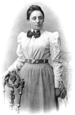
Einstein referred to her as the most important woman in the history of mathematics. Her theorem has been recognized as “one of the most important mathematical theorems ever proved in guiding the development of modern physics.” Yet many people haven’t the slightest clue of who this woman was, or what she did that was so significant to our understanding of how our world works. If you count yourself as one of those who have never heard of Emmy Noether and wish to enlighten yourself, please read on. I can only hope I do her memory justice. Not just by telling you who she was, but by also giving you an understanding of how her insight led to the coming together of symmetry and quantum theory, pointing academia’s arrow toward quantum electrodynamics.
Being a female in Germany in the late 1800s was not easy. She wasn’t allowed to register for math classes. Fortunately, her father happened to be a math professor, which allowed her to sit in on many of his classes. She took one of his final exams in 1904 and did so well that she was granted a bachelors degree. This allowed her to “officially” register in a math graduate program. Three years later, she earned one of the first PhD’s given to a woman in Germany. She was just 25 years old.
1907 was a very exciting time in theoretical physics, as scientists were hot on the heels of figuring out how light and atoms interact with each other. Emmy wanted in on the fun, but being a woman made this difficult. She wasn’t allowed to hold a teaching position, so she worked as an unpaid assistant, surviving on a small inheritance and under-the-table money that she earned sitting in for male professors when they were unable to teach. She was still able to do what professors are supposed to do, however – write papers. In 1916, she would pen the theorem that would have her rubbing shoulders with the other physics and mathematical giants of the era.
Noether’s Theorem – The Basics
Emmy Noether’s Theorem seems simple on the onset, but holds a fundamental truth that explains the fabric of our reality. It goes something like this:
For every symmetry, there is a corresponding conservation law.
We all have heard of laws such as Newton’s first law of motion, which is about the conservation of momentum. And the first law of thermodynamics, which is about the conservation of energy. Noether’s theorem tells us that there must be some type of symmetry that is related to these conservation laws. Before we get into the meaning, we must first understand a little known subject called The Principle of Least Action.
The Universe is Lazy
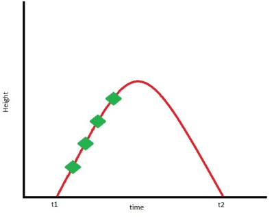
I would wager a few Raspberry Pi Zeros that many of you already have an intuitive grasp of this principle, even if you’ve never heard of it before now. The principle of least action basically says that the universe has figured out the easiest way possible to get something done. Mathematically, it’s the sum over time of kinetic energy minus potential energy as the action occurs. Let us imagine that you’re trying to program an STM32 Discovery eval board in GCC. After about the 6,000th try, you toss the POS across the room and grab your trusty Uno. The graph depicts the STM32 moving through time and space.
The green points represent particular points of how how high the STM32 is at a given point in time. Note that there are no values for height and time – this example is meant to explain a principle. We can say that at these points (and all points along the curve), the SMT32 has both kinetic and potential energies. Let us call the kinetic energy (kt) and the potential energy (pt). The ‘t‘ subscript is for time, as both the energies are functions of time. The action for each point will be called s, and can be calculated as:
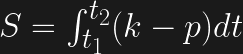
However, action is the total sum of the difference of energies at each point between t1 and t2. If you’ve read my integral post, you will know that we need to integrate in order to calculate the total action.
Now before you get your jumper wires in a bunch, all that is saying is that we’re taking the difference in potential (p) and kinetic (k) energies at each point along the curve between t1 and t2, and we’re adding them together. The elongated S symbol means a sum, and the (dt) means as it changes over time. The path that the STM32 will take will be the path where the action S is at its minimum value. Check out the video in the source section below if you’re confused. It’s only 10 minutes and goes into this concept in easy to follow details.
Noether’s Theorem – The Details
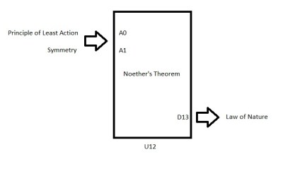
Noether’s theorem is based upon a mathematical proof. It’s not a theory. Her proof can be applied to physics to develop theories, however. Now that we know what the principle of least action is, we can do just this.
Any law of nature can be traced back to a symmetry and the least action principle. Let’s consider two very simple examples – Newton’s first law of motion and the first law of thermodynamics.
Conservation of Momentum
Space has what is known as translational symmetry. That’s just fancy-pants talk for saying that what you do in one point in space is the same as what you do in another point in space. It doesn’t matter what hacker space you throw your STM32, it will act the same at all hacker spaces on earth. Space itself provides the symmetry. And because the principle of least action applies, you have a natural law – the first law of motion.
Conservation of Energy
Time has the same translational symmetry as space does. If I toss the STM32 now, and toss it tomorrow, it will act the same. It doesn’t matter what point in time I toss it, the results will always be the same. Thus energy is conserved between different points in time. Time is our symmetry, and the 1st law of thermodynamics is the result.
Now, I realize these examples might seem a bit useless. But when you dig a bit deeper, things get interesting. Electrical charge is also conserved. Noether says there must then be some type of symmetry involved. What do you suppose that symmetry might be? Keep following that rabbit hole, and you’ll end up face to face with QED. We’ll get there in a future article, so for now just keep Noether’s Theorem in mind.
Sources
Physics Helps, The principle of least action, video link.
Ransom Stephens, Ph.D., Emmy Noether and The Fabric of Reality, video link
3D Hubs, the distributed ‘3D printing service’ thing, now has 30,000 machines distributed around the globe. They also put together the definitive guide to 3D printing recently. For just about everyone reading this, a ‘introduction to 3D printing’ is old news, but this is a very good guide for telling your weird aunt what you’re building in the basement. Forward this one to your family on Facebook.
This one is amazing. Over on Hackaday.io, [Arsenijs] is working on a Raspberry Pi project. It uses a Raspberry Pi, and several accessories and components to make this Raspberry Pi project work. This Raspberry Pi project is already getting far more than the usual number of likes and follows, making this one of the most interesting Raspberry Pi projects in recent memory.
Moog is re-releasing the Minimoog, the original Moog synth from 1970. That’s cool, but what about a DIY Minimoog? That’s what [Scott Rider] is doing with the Crowminius Analog Music Synthesizer on Kickstarter. It’s an analog synth that’s more or less a Minimoog with MIDI, and one of the Kickstarter rewards is a bare PCB.
What do you do when you need to get your Hackaday fix, but all you have is a laptop from 1995 and a dial-up modem? The Hackaday Retro Edition, of course. That’s a bunch of retro Hackaday posts, posted five at a time, with all the CSS and JavaScript cruft stripped. We’re always interested to see the old machines that are pulling the retro edition down, and [djnikochan] has the latest entry. He found a Thinkpad 380ED from 1997 at the Goodwill store for $15. The RAM was upgraded with a 64MB SIMM, giving this machine a total of 80MB. The Hackaday Retro Edition is viewable with IE 5.5 over a trusty PCMICA WiFi card. Awesome job, and we love to see old iron rendering the retro edition. Send some pics in if you get your old battlestation to load it.
It is not often that you look for one of your heroes on the Internet and by chance encounter another from a completely different field. But if you are a fan of the inimitable silent movie star [Buster Keaton] as well as being the kind of person who reads Hackaday then that could have happened to you just as it did here.
Our subject today is a 1957 episode of CBS’s TV game show I’ve Got a Secret! in which [Keaton] judges a pie-eating contest and is preceded first by a young man with a penchant for snakes and then rather unexpectedly by a true giant of twentieth century technology.
[Philo T Farnsworth] was a prolific engineer who is probably best known as the inventor of electronic television, but whose work touched numerous other fields. Surprisingly this short segment on an entertainment show was his only appearance on the medium to which his invention helped give birth. In it he baffles the panel who fail to guess his claim to fame, before discussing his inventions for a few minutes. He is very effacing about his achievement, making the point that the development of television had been a cumulative effort born of many contributors. He then goes on to discuss the future of television, and talks about 2000-line high-definition TV with a reduced transmission bandwidth, and TV sets like picture frames. All of which look very familiar to us nearly sixty years later in the early 21st century.
The full show is below the break, though [Farnsworth]’s segment is only from 13:24 to 21:24. It’s very much a show of its time with its cigarette product placement and United Airlines boasting about their piston-engined DC-7 fleet, but it’s entertaining enough.
Last week on the Hacklet we covered optical microscopy projects. Those are the familiar scopes that many of us have at work or even at home on our benches. These are scopes that you typically can use with your eye, or an unmodified camera. This week we’re taking a look at more extreme ways of making small things look big. Electron streams and the forces of a single atom can be used to create incredibly magnified images. So let’s jump right in and check out the best advanced microscopy projects on Hackaday.io!
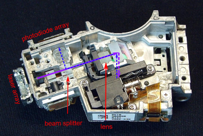
We start with [andreas.betz] and BluBEAM – a scanning laser microscope. [Andreas] aims to create a scanning confocal microscope. The diffraction limit is the law of the land for standard optical microscopes. While you can’t break the law, you can find ways around it. Confocal microscopy is one technique used quite a bit in medicine and industry. Confocal scopes are generally very expensive, well outside the budget of the average hacker. [Andreas] hopes to break that barrier by creating a scanning confocal microscope using parts from a PlayStation 3 Blu-Ray optical drive. Optical drives use voice coils to maintain focus. [Andreas] had to create a custom PCB with a voice coil driver to operate the PS3 optics assembly. He also needed to drive the laser. BluBeam is still very much a work in progress, so keep an eye on it!
Next up is [MatthiasR.] with DIY Scanning tunneling microscope. Open atmosphere scanning tunneling microscopes are popular on Hackaday.io. I covered [Dan Berard]’s creation in Hacklet 103. Inspired by Dan, [Matthias] is building his own STM.
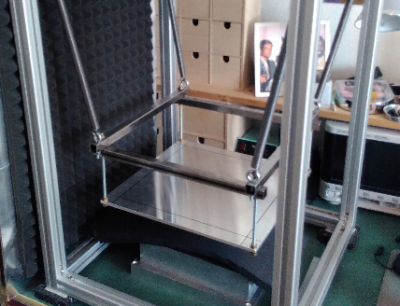
Environmental vibration is a huge problem with high magnification microscopes. [Matthias] is combating this by building a vibration isolation platform using extruded aluminum. He’s currently working on the STM preamplifier, which amplifies and converts the nano amp STM values to voltages which can be read by a digital to analog converter. [Matthias] is using the venerable Analog ADA4530 for this task. With an input bias of 20 femtoamps (!) it should be up to the task.
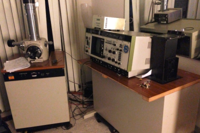
Next we have [Jerry Biehler] AKA [macona] with Hitachi S-450 Scanning Electron Microscope. Scanning electron microscopes have to be the top of the microscopy food chain. Jerry got his hands on a 1980’s vintage Hitachi SEM which was no longer working. The problem turned out to be a dodgy repair made years earlier with electrical tape. Fast forward a couple of years of use, and [Jerry] has done quite a lot to his old machine. He’s learned how to make his own filaments from tungsten wire. The slow oil diffusion vacuum pump has been replaced with a turbomolecular pump. The SEM now resides in [Jerry’s] living room, which keeps it at a relatively constant temperature.
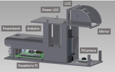
Finally, we have [beniroquai] with Holoscope – Superresolution Holographic Microscope. Holoscope is a device which increases the resolution of a standard camera by using the physical properties of light to its advantage. Precise tiny shifts of the object being magnified cause minute changes in a reflected image, which is captured by a Raspberry Pi camera. The Pi can then reconstruct a higher resolution image using the phase data. [beniroquai] has put a lot of time into this project, even sacrificing an expensive Sony connected camera to the ESD gods. I’m following along with this one. I can’t wait to see [beniroquai]’s first few images.
If you want to see more advanced microscopy projects, check out our new advanced microscope projects list! If I missed your project, don’t be shy, just drop me a message on Hackaday.io. That’s it for this week’s Hacklet. As always, see you next week. Same hack time, same hack channel, bringing you the best of Hackaday.io!
I could have sworn that we have asked this one before, but perhaps I’m thinking of our discussion of nuclear aircraft. In my mind the two share a similar fate: it just isn’t going to happen. But, that doesn’t mean flying cars can’t happen. Let me make my case, and then we want to know what you think.
[Steve] sent in a link to a Bloomberg article on Larry Page’s suspected investment in personal flying cars. It’s exciting to hear about test flights from a startup called Zee.Aero with 150 people on staff and a seemingly unlimited budget to develop such a fantastic toy. Surely Bruce Wayne Mr. Page is onto something and tiny 2-person vehicles will be whizzing up and down the airspace above your street at any moment now? Realistically though, I don’t believe it. They definitely will build a small fleet of such vehicles and they will work. But you, my friend, will never own one. Continue reading “Ask Hackaday: Where Are The Flying Cars?”→
Makerbot is in the gutter, 3D Systems and Stratasys stock is only a shadow of their 2014 glory, but this is the best year 3D printing has ever had. Machines are now good and cheap, there’s a variety of various thermoplastic filaments, and printing useful objects – instead of just plastic trinkets – is becoming commonplace.
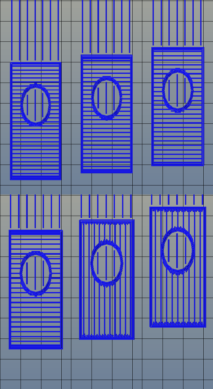
The standard rectilinear infill from Slic3r
There’s one area of 3D printing that hasn’t seen as much progress, and it’s the software stack. Slicing, the process of turning a 3D object into a Gcode file for a printer has been basically the same for the last few years. Dual extrusion is still a mess, and automated bed leveling is still in its infancy.
One aspect of slicing that has been severely overlooked is infill. Obviously, you don’t want to print plastic trinkets completely solid – only the outside surface matters, and a part with 100% infill is just a waste of plastic. Different slicers have come up with different ways of filling the inside of a print, usually with a grid of squares, triangles, or hexagons.
While the most popular methods of filling in a 3D printed objects do the job of adding a little bit of strength to a print and supporting the top layers of a print, it’s not an ideal solution. The desired strength of the finished part is never taken into account, print artifacts are sometimes visible through the side of a print, and the spacing of the infill grid is completely arbitrary. You can only set a percentage of infill, and telling a slicer to make an internal support grid with 10mm spacing is impossible.
Type A Machines just changed all of this. With the release of their public beta of Cura Type A, the infill for a 3D printed part is also 3D. The dimensions of the infill are predictable, opening the door to stronger and better looking parts.
From the Type A press literature and white paper, this new type of ‘infill’ isn’t; it’s more properly referred to as ‘internal structure’, with proper dimensions between infill features. Instead of a grid of squares or triangles stacked one layer on top of each other, it’s a true structure, with the infill following the perimeter of the 3D printed object.
Generating 3D Infill
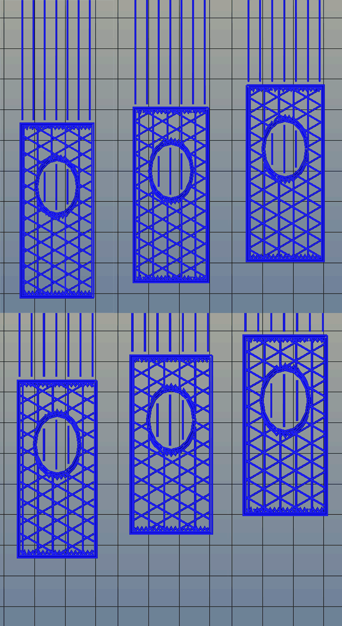
Infill generated from Type A Machine’s Cura beta. Note the 3D structure of the infill.
Right now, infill is generated in a slicer by specifying a percentage. Zero percent infill means a hollow object, and 100% infill is a completely solid part. These two edge cases are easy, but anything else means the slicer must fill the part with filament in a grid of tessellating shapes, either rectangles, triangles, or hexagons. With current slicers, the dimensions of this internal structure are, for all practical purposes, random. Printing an object with 20% infill might mean a grid of squares with 5mm or 2mm spacing. Telling the slicer to infill a part with a grid of squares spaced 10mm apart is impossible.
Type A Machine’s latest Cura release changes all of this, allowing a designer to set a precise distance between rows and columns of infill. By defining infill in absolute dimensions, this allows for stronger parts using less infill.
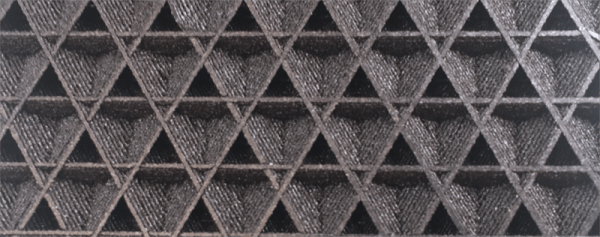
Absolute dimensioning is only one feature of the Type A Machine’s latest release of Cura. Even more exciting is the development of 3D internal structure. Instead of stacking layers of squares, triangles, or hexagons on top of each other, Type A Machine’s Cura uses an infill of cubes turned on their side. While each individual layer of infill looks like a series of triangles and irregular hexagons, when assembled into a printed 3D object, this infill forms a true 3D structure.
The closest comparison to this sort of structure is the difference between graphite and diamond. Both of these materials are made out of the same element, carbon. The physical structure of graphite is just, 1-atom-thick layers of graphene, producing a relatively weak material. Diamond, on the other hand, has a true 3D structure and is one of the hardest materials known to man. While adding 3D structure to the infill of 3D printed objects won’t make the objects any stronger, it will drastically reduce delamination, and be much more resistant to stresses in all three dimensions.
While Type A Machines has done some great work here, it does mean there’s yet another version of Cura to deal with. Type A Machine’s Cura, in addition to the LulzBot edition and the original are now the defacto standard for turning 3D objects into printed parts. Having an open source solution is great, but forking the development this much surely can’t be ideal.


 I would wager a few Raspberry Pi Zeros that many of you already have an intuitive grasp of this principle, even if you’ve never heard of it before now. The principle of least action basically says that the universe has figured out the easiest way possible to get something done. Mathematically, it’s the sum over time of kinetic energy minus potential energy as the action occurs. Let us imagine that you’re trying to program an STM32 Discovery eval board in GCC. After about the 6,000th try, you toss the POS across the room and grab your trusty Uno. The graph depicts the STM32 moving through time and space.
 Noether’s theorem is based upon a mathematical proof. It’s not a theory. Her proof can be applied to physics to develop theories, however. Now that we know what the principle of least action is, we can do just this.