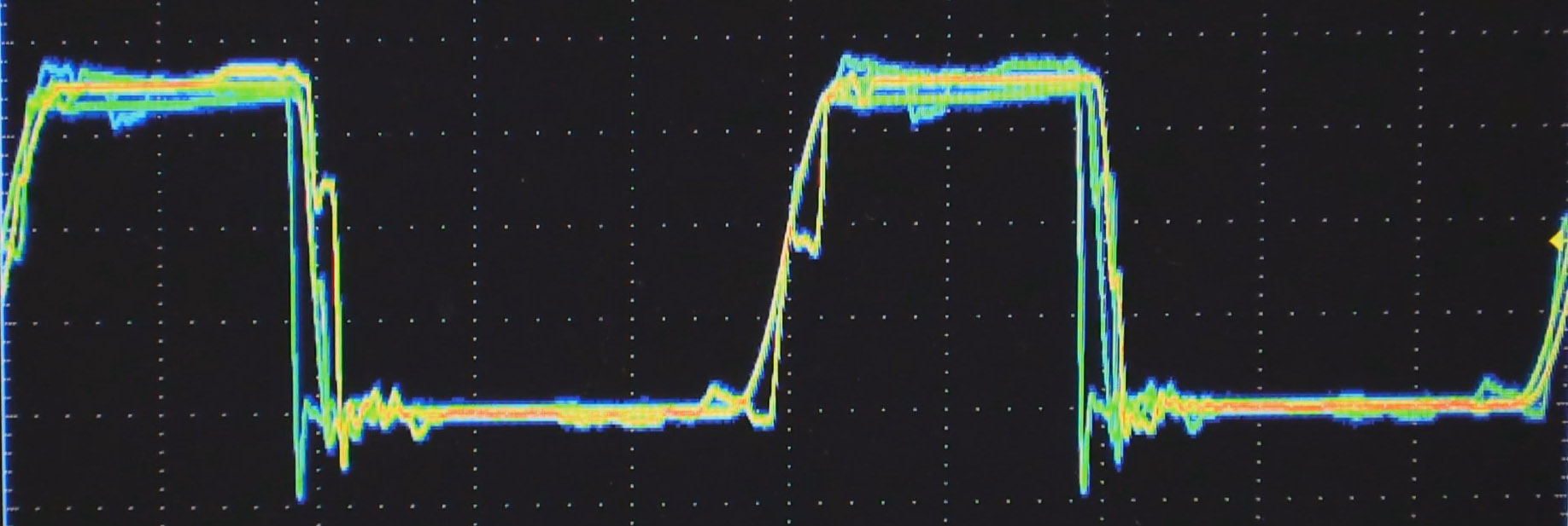
On the path to exploring complex logic, let’s discuss the electrical properties that digital logic signals are comprised of. While there are many types of digital signals, here we are talking about the more common voltage based single-ended signals and not the dual-conductor based differential signals.
Single-ended Logic Signal
I think of most logic as being in one of two major divisions as far as the technology used for today’s logic: Bipolar and CMOS. Bipolar is characterized by use of (non-insulated gate) transistors and most often associated with Transistor Transistor Logic (TTL) based logic levels. As CMOS technology came of age and got faster and became able to drive higher currents it began to augment or offer an alternative to bipolar logic families. This is especially true as power supply voltages dropped and the need for low power increased. We will talk more about CMOS in the next installment.
TTL was a result of a natural progression from the earlier Resistor Transistor Logic (RTL) and Diode Transistor Logic (DTL) technologies and the standards used by early TTL became the standard for a multitude of logic families to follow.
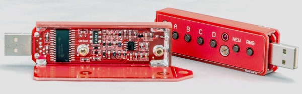
How can you generate random bits? Some people think it’s not easy, others will tell you that it’s pretty damn hard, and then there are those who wonder if it is possible at all. Of course, it is easy to create a very long pseudorandom sequence in software, but even the best PRNG (Pseudorandom Number Generator) needs a good random seed, as we don’t want to get the same sequence each time we switch on the unit, do we? That’s why we need a TRNG (True Random Number Generator), but that requires special hardware.
Some high-end microprocessors are equipped with an internal hardware TRNG, but it is, unfortunately, not true for most low-cost microcontrollers. There are a couple of tricks hackers use to compensate. They usually start the internal free running counter and fetch its contents when some external event occurs (user presses a button, or so). This works, but not without disadvantages. First, there is the danger of “locking” those two events, as a timer period may be some derivative of input scan routine timing. Second, the free running time (between switching on and the moment the unit requests a random number) is often too short, resulting in the seed being too close to the sequence start, and thus predictable. In some cases even, there is no external input before the unit needs a random seed!
Despite what has already been discussed, microcontrollers do have a source of true randomness inside them. While it might not be good enough for crypto applications, it still generates high enough entropy for amusement games, simulations, art gadgets, etc.
SparkFun, you know them, you love them. They list themselves as “an online retail store” but I remember them for well-designed breakout boards, free-day, videos about building electronics, and the Autonomous Vehicle Competition. This week SparkFun turned my head for a different reason with the announcement that [Nathan Siedle], founder and CEO will be stepping down. He’s not leaving, but returning to the Engineering department while someone else takes the reigns. I spoke with him yesterday about what this means for him, the company, and what SparkFun has planned for the future.
Stepping Down Without Saying Goodbye
[Nate] founded Sparkfun in 2003 while still working on his Electrical Engineering degree from the University of Colorado Boulder. He cites wanting to return to his engineering roots as the reason for his title shift, which won’t happen for at least 9 or 10 months. It’s the concept of leaving the CEO position without leaving the company that raises many questions in my mind.
It’s an interesting proposition; there is no company serving the maker community – and those of us who refuse to call ourselves part of the maker community – more hated than MakerBot. They’ve patented ideas uploaded to Thingiverse. They’ve turned their back on the open hardware community they grew out of, They’re undercutting their own resellers, and by all accounts, they don’t know how to make a working extruder. MakerBot was the company that would show the world Open Hardware could be successful, but turned into a company that seemed to reject Open Hardware and Open Source more than any other.
Nevertheless, questions were collected, The MakerBot CEO was interviewed by Lady Ada, and a summary compiled. You can check that interview, originally posted on the Adafruit blog, below.
Last week we started the first round of community voting for The Hackaday Prize, where everyone on Hackaday.io has a voice in choosing the best project for the current theme of the week. To encourage people to vote, we’re giving away a $1000 gift card to The Hackaday Store to one person on hackaday.io if they have voted in the latest round of community voting. How are we doing that? A very, very large die and SQL queries:
No, no one won this week. That’s okay, because we’re giving t-shirts away to three random people who did vote. This week, [cgapeart], [Jeff], and [devonelliott] are getting t-shirts from the Hackaday Store, just because they were cool enough to vote.
We’re going to keep this round of community voting going for another week. Everyone registered on Hackaday.io gets 50 votes for each round of voting, and every Friday (around 20:00 UTC), we’ll randomly select one person registered on Hackaday.io. If that person has voted, they get a $1000 gift card for The Hackaday Store. If they haven’t voted — a t-shirt. They’re nice t-shirts, but I’d rather have the gift card.
All you have to do for a chance to win a $1000 gift card is head over to the Community Voting Page and pick which project is most likely to be widely used. There’s no wrong answer; all you have to do is decide between two projects. If you only use up one vote, you’re in the running for a $1000 gift card.
I’ll be doing another round of random, fair die rolls and SQL queries next Friday. Until then, VOTE!
Most hobbyists say that it is easier to build a functional prototype of an electronic device, than to make the enclosure for it. You could say that there are a lot of ready-made enclosures on the market, but they are never exactly what you need. You could also use a 3D printer to build a custom enclosure, but high-end 3D printers are too expensive, and the cheaper ones produce housings which are often not robust enough, and also require a lot of additional treatment.
Another way is to build the enclosure out of FR4, a material which is commonly used in PCB production. Such enclosures are low-cost, with thin walls but yet very strong, nice looking, pleasant to the touch and have excellent thermal and moisture stability. FR4 offers some more possibilities – efficient wiring with no wires inside the housing, integrated UHF or SHF antennas or RFID coils, capacitive switches, electrical shielding, selective semi-transparency, water or air tightness, and even integration of complex mechanical assemblies.
Here I shall explain the process of building those “magic” enclosures. It is based on nearly fifty years of personal experience and more than a hundred enclosures, built for most of my projects. Here are two examples – this case for a hardware password manager is just a few centimeters long, while the other one (protective transportation cover for my son’s synthesizer) measures 125cm (about 49 inches), and yet both of them are strong enough to withstand a grown man standing on top of them.
The global approach is simple – you take the sheet of single-sided copper clad FR4, cut it and solder the parts together. That sounds simple, but there are a lot of details which should be met if you want to get top results. Please read about them carefully. You might be tempted to skip some of the steps described here, but if you do so, you will most likely end up being disappointed with the results.
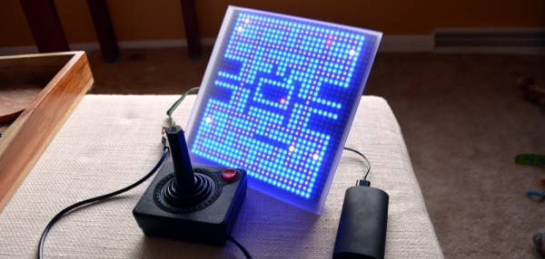
I usually see retro-gaming projects using tiny screens with a fair number of pixels (64×64) but what I really like is the look of making every pixel count. With this in mind I built 1-Pixel Pac-Man, the classic coin-op experience but with characters that consist of just one pixel. Playing a throw-back like this wouldn’t be the same without some vintage controls so I picked up an Atari joystick, patched it into a microcontroller, and started coding. Check it out:
Smartmatrix Bundle
32×32 RGB panel with acrylic diffuser
Back of the Smartmatrix
This piece of hardware made the project build really easy: the Smartmatrix. [Louis Beaudioin] developed the Smartmatrix and it’s been in the Hackaday Store for a while now. The display module itself is a commodity item that is used in LED billboards. There are shrouded headers on the back of the panels, to the left and right sides, which allow them to be daisy chained. The Smartmatrix PCB plugs into one of these shields, provides a soldering footprint for the Teensy 3.1 which drives the display, and gives you the wiring to connect screw terminals from the PCB to the power terminals on the module. Why the need for beefy power jumpers? At full white the thing can draw about 3.5A — don’t worry there’s a power supply included in the bundle.
Also integral to making this look good is the diffuser panel which is frosted acrylic. The Smartmatrix is designed to be housed in a shadowbox frame; it even includes a frame backer board with a cut-out for the Teensy 3.1 so it can be programmed without opening the thing up. I like looking at the guts so I’m leaving my free floating until I come up with an interesting way to mount everything as one unit.
Programming Pac-Man from the Ground Up
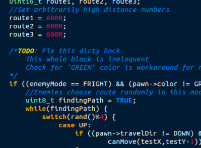
If you haven’t looked into it before, the ghost AI and gameplay details for Pac-Man are absolutely brilliant. [Toru Iwatani] did a masterful job with the original, and you should take a look at all of the analysis that has been done over the years. The best collection I could find was the Pac-Man Dossier and I based most of my code on the rules described there.
Basically the ghosts have two modes, chase and scatter. The modes set the enemy targets differently; to points at the four corners of the board in scatter, and to points relative to the player in chase. The relative part is key; only the red enemy actually chases you. Another one of them looks at the red enemy’s distance and angle, and targets the reflection of that vector. Really easy, really clever, and results in enemy behavior that’s believable. It isn’t just the enemy movement, little touches like a speed penalty (1/60 of a second) for each dot the player gobbles up means the enemies can catch up if you continuously eat, but you can escape by taking the path already-eaten.
Library, DMA, and Extra Hardware
Teensy 3.1
DB9 Connector for Joystick
Extras in the Bundle
Kickstarter remote and RTC Module
The hardware and software running the Smartmatrix made the display portions of the project really simple. First off, the Teensy 3.1 is fast, running at 96MHz in this case. Second, it has Direct Memory Access (DMA) which [Louis] used in the Smartmatrix library. This means that driving the display takes almost no CPU time at all, leaving the rest for your own use. This example of a game is under-utilizing this power… it’s totally capable of full-motion video and calculating amazing visualizations on the fly.
The PCB hosting the Teensy 3.1 breaks out several pins to one side. I’m not sure what I’ll add in the future so I actually used the extra surface-mount IO pins on the bottom of the Teensy to connect the Atari joystick (which is simply a set of switches). The are enough pads for two joysticks so I used pin sockets to interface the Teensy to the PCB so that I can get to it again later.
The kit also includes an IR receiver and remote, and also a microSD card to loading animations (there’s an SD socket on the PCB). The bundle in the Hackaday Store is a kit you solder yourself, but [Louis’] company, Pixelmatix, has a Kickstarter running for fully-assembled versions that come with a black remote and sound-visualization hardware.
Future Improvements
The game is fully working, but there are a few key things that I really want to add. The Teensy 3.1 has a single DAC pin available. I’m fairly certain the original coin-op game had mono audio. It should be possible to reproduce the sound quite accurately with this board. That would really make the project pop.
There are also a bunch of touch-ups that need to happen. I’d like to add an animation when the player is eaten by an enemy, and a countdown before the level restarts. The score, shown in binary on the right column, should be scrolled out in decimal when the game ends, and what’s a coin-op recreation without a high-score screen?