We often think of 3D printing as a way to create specific components in our builds, everything from some hard-to-find little sprocket to a custom enclosure. More and more of the projects that grace the pages of Hackaday utilize at least a few 3D printed parts, even if the overall build itself is not something we’d necessarily consider a “printed” project. It’s the natural progression of a technology which at one time was expensive and complex becoming increasingly available to the maker and hacker.
 But occasionally we see 3D printing used not to create new devices, but recreate old ones. A perfect example is the almost entirely 3D printed telegraph system created by [Matt]. Projects like this help bring antiquated technology back to a modern audience, and can be an excellent educational tool. Showing someone a diagram of how the telegraph worked is one thing, but being able to run off a copy on your 3D printer and putting a working model in their hands is quite another.
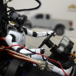
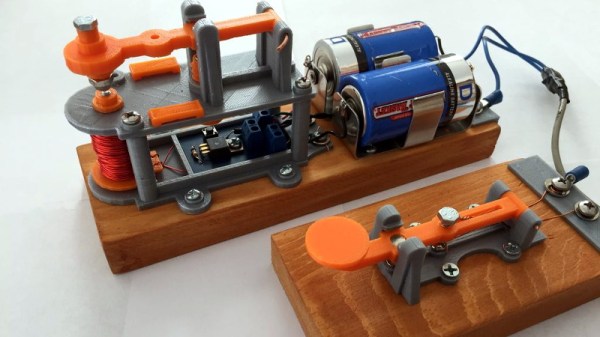
[Matt] acknowledges that he’s hardly the first person to 3D print a telegraph key, but says that he’d never seen the complete system done before. The key is perhaps the component most people are familiar with from film and old images, but alone it’s really nothing more than a momentary switch. To actually put it to use, you need a telegraph sounder on the receiving end to “play” the messages.
The sounder is a somewhat more complex device than the key, and uses an electromagnet to pull down a lever and produce an audible clicking noise. In the most basic case, the coil is directly connected to the key, but in a modern twist [Matt] has added a MOSFET into the circuit so the electromagnet is triggered locally within the sounder. This prevents sparks from eroding the contacts in the key, and alleviates problems associated with current loss over long wire runs.
We’ve previously seen 3D printing used to revive vintage games which are no longer available such as “The Amazing Dr. Nim”, and how modern techniques such as additive manufacturing can help put World War II aircraft back in the air. While there was never much question that 3D printing would be a big part of our future, it would seem to be taking a fairly active role in preserving our past as well.
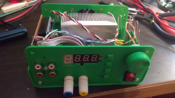
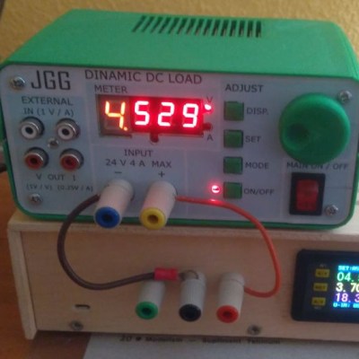 The first thing to catch one’s eye might be that leftmost seven-segment digit. There is a simple reason it doesn’t match its neighbors: [Juan] had to use what he had available, and that meant a mismatched digit. Fortunately, 3D printing one’s own enclosure meant it could be gracefully worked into the design, instead of getting a Dremel or utility knife involved. The next is a bit less obvious: the display lacked a decimal point in the second digit position, so an LED tucked in underneath does the job. Finally, the knob on the right could reasonably be thought to be a rotary encoder, but it’s actually connected to a small DC motor. By biasing the motor with a small DC voltage applied to one lead and reading the resulting voltage from the other, the knob’s speed and direction can be detected, doing a serviceable job as rotary encoder substitute.