There’s a lot going on our virtual spaces, and anyone with a smart phone can attest to this fact. There are pop-up notifications for everything you can imagine, and sometimes it’s possible for the one really important notification to get lost in a sea of minutiae. To really make sure you don’t miss that one important notification, you can offload that task to your own personal dinosaur.
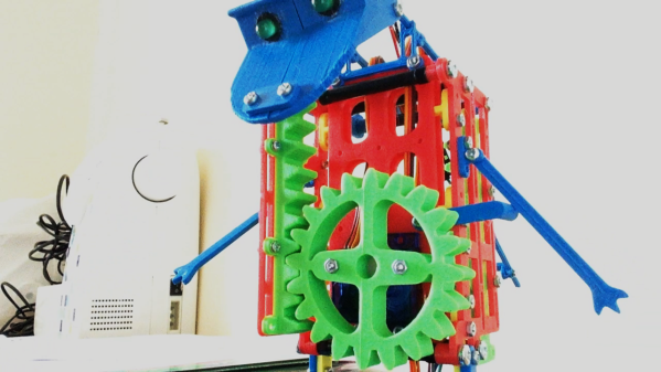
The 3D-printed dinosaur has a rack-and-pinion gear set that allows it to extend upwards when commanded. It also has a set of LEDs for eyes that turn on when it pops up. The two servos and LEDs are controlled by a small Arduino in the base of the dinosaur. This Arduino can be programmed to activate the dinosaur whenver you like, for an email from a specific person, a reply to a comment on Reddit, or an incoming phone call to name a few examples. Be sure to check out the video below the break.
Part of what makes flamethrowers fun is their inherent danger. This is what makes a lot of things fun, though, from snowboarding to skydiving to motorcycle riding. As with all of these sensible hobbies, though, it’s important to take as much unnecessary risk out of the activity as possible to make sure you’re around as long as possible to enjoy your chosen activity. With that in mind, [Stephen] decided to make some improvements on his classic wrist-mounted flamethrower.
To start, he ditched the heavy lead-acid battery that powered the contraption in favor of a smaller 5 V battery. In fact, the entire build is much more compact and efficient. He was also able to use the same battery to run a tiny taser that acts as an ignition source for the flamethrower’s fuel. The fuel itself is butane, and the modified flamethrower is able to launch flames much further than the original due to improvements in the fuel delivery system. These improvements also include “Finding a way to prevent butane droplets from lighting and landing on [his] hand” which seems like a necessary feature as well.
The entire build now is very well refined and professional-looking, which is also a major improvement from the first version. It’s also worth watching the video after the break as well, which includes a minor run-in with the New York City fire marshal. And, it still retains some of the danger and all of the fun of the original builds which is something we always like to see.
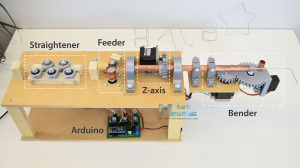
It’s been a while since we’ve shown a DIY wire bending machine, and [How To Mechatronics] has come up with an elegant design with easy construction through the use of 3D-printed parts which handle most of the inherent complexity. This one also has a Z-axis so that you can produce 3D wire shapes. And as with all wire bending machines, it’s fun to watch it in action, which you can do in the video below along with seeing the step-by-step construction.
One nice feature is that he’s included a limit switch for automatically positioning the Z-axis when you first turn it on. It also uses a single 12 volt supply for all the motors, and the Arduino that acts as the brains. The 5 volts for the one servo motor is converted from 12 using an LM7805 voltage regulator. He’s also done a nice job packaging the Arduino, stepper motor driver boards, and the discrete components all onto a single custom surface mount PCB.
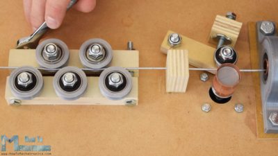
Wire straightener and feeder
The bender isn’t without some issues though, such as that there’s no automatic method for giving it bending instructions. You can write code for the steps into an Arduino sketch, which is really just a lot of copy and paste, and he’s also provided a manual mode. In manual mode, you give it simple commands from a serial terminal. However, it would be only one step more to get those same commands from a file, or perhaps even convert from G-code or some other format.
Another issue is that the wire straightener puts too much tension on the wire, preventing the feeder from being able to pull the wire along. One solution is to feed it pre-straightened wire, not too much to ask for since it’s really the bending we’re after. But fixing this problem outright could be as simple as changing two parts. For the feeder, the wire is pulled between copper pipe and a flat steel bearing, and we can’t help wondering whether perhaps replacing them with a knurled cylinder and a grooved one would work as the people at [PENSA] did with their DIWire which we wrote about back in 2012. Sadly, the blog entries we linked to no longer work but a search shows that their instructable is still up if you want to check out their feeder parts.
As for the applications, we can think of sculpting, fractal antennas, tracks for marble machines, and really anything which could use a wireframe for its structure. Ideas anyone?
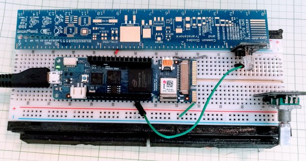
If you speak French and you have an Arduino Vidor 4000, you are in luck because there’s some good news. The good news is there’s finally some inside information about how to configure the onboard FPGA yourself. The bad news though is that it is pretty sparse. If your high school French isn’t up to the task, there’s always Google Translate.
We knew some of this already. You’ll need Quartus, the FPGA design tool from Altera — er, Intel — and we know about the sample project on GitHub, too. Instead of using conventional Verilog or VHDL, the new information uses schematic capture, but that’s OK. All the design entry winds up in the same place, so it should be easy to adapt to the language of your choice. In fact, in part 2 they show both some schematics and some Verilog. Google Translate does have a little trouble with code comments, though. If you want something even stouter, there’s an example that uses Verilog to output a video frame.
For a five-year-old future Hackaday scribe, there could be no greater day than that on which a Dymo label maker appeared in the house. With its spinny daisy-wheel to choose a character and its squeezy handle to emboss the letter into the plastic tape, there would follow a period of going nuts kerchunking out misspelled labels and slapping them on everything. Plus the things look like space guns, so there would have been a lot of pew-pewing too.
This Dymo dot-matrix label maker bears no resemblance to our long-lost label blaster, but it’s pretty cool in its own right. The product of collaborators [Felix Fisgus] and [Timo Johannes] and undertaken as a project for their digital media program, the only thing the labeler has in common with the Dymos of old is the tape. Where the manual labelers press the characters into the tape with a punch and die, their project uses a dot-matrix approach. Messages are composed on an old PS/2 keyboard through an Arduino and a 16×2 LCD display, and punched onto the tape a dot at a time. The punch is a large darning needle riding on the remains of an old CD drive and driven by a solenoid. When it comes time to cut the label, servo driven scissors do the job. It’s a noisy, crazy, Rube Goldberg affair, and we love it. Check it out in action in the video below.
We applaud [Felix] and [Timo] for carrying the torch of embossed label making. It’s a shame that we’ve turned to soulless thermal printers to handle most of our labeling needs; then again, we’ve seen some pretty neat hacks for those too.
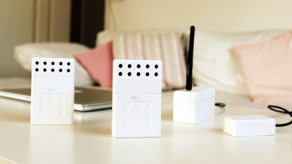
Sensor network projects often focus primarily on electronic design elements, such as architecture and wireless transmission methods for sensors and gateways. Equally important, however, are physical and practical design elements such as installation, usability, and maintainability. The SENSEation project by [Mario Frei] is a sensor network intended for use indoors in a variety of buildings, and it showcases the deep importance of physical design elements in order to create hardware that is easy to install, easy to maintain, and effective. The project logs have an excellent overview of past versions and an analysis of what worked well, and where they fell short.
One example is the power supply for the sensor nodes. Past designs used wall adapters to provide constant and reliable power, but there are practical considerations around doing so. Not only do power adapters mean each sensor requires some amount of cable management, but one never really knows what one will find when installing a node somewhere in a building; a power outlet may not be nearby, or it may not have any unoccupied sockets. [Mario] found that installations could take up to 45 minutes per node as a result of these issues. The solution was to move to battery power for the sensor nodes. With careful power management, a node can operate for almost a year before needing a recharge, and removing any cable management or power adapter meant that installation time dropped to an average of only seven minutes.
That’s just one example of the practical issues discovered in the deployment of a sensor network in a real-world situation, and the positive impact of some thoughtful design changes in response. The GitHub repository for SENSEation has all the details needed to reproduce the modular design, so check it out.
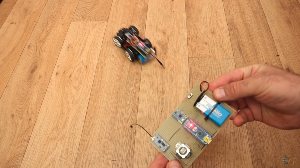
If you are a lover of all-things remote-conteolled, it’s likely that you know a thing or two about controllers. You’ll have one or two of the things, both the familiar two-joystick type and the pistol-grip variety. But had you ever considered that there m ight be another means to do it? [Andrei] over at ELECTRONOOBS has posted a guide to a tilt-controlled RC car. It is a good example of how simple parts can be linked together to make something novel and entertaining, and a great starter project for an aspiring hacker.
An Arduino Nano reads from an accelerometer over an I2C bus, and sends commands over a wireless link, courtesy of a pair of HC-12 wireless modules. Another Nano mounted to the car decodes the commands, and uses a pair of H-bridges, which we’ve covered in detail, to control the motors.
The tutorial is well done, and includes details on the hardware and all the code you need to get rolling. Check out the build and demo video after the break.